REV 0, June 2005Page 46
Operation Manual SUPREMA
4. Operation of the System
If an input is selected using the cursor keys and the ↵ key then the data for the selected input,
at the moment the key was pressed, is displayed for as long as the key is held down. There is
no graphic updating of input data during this time.
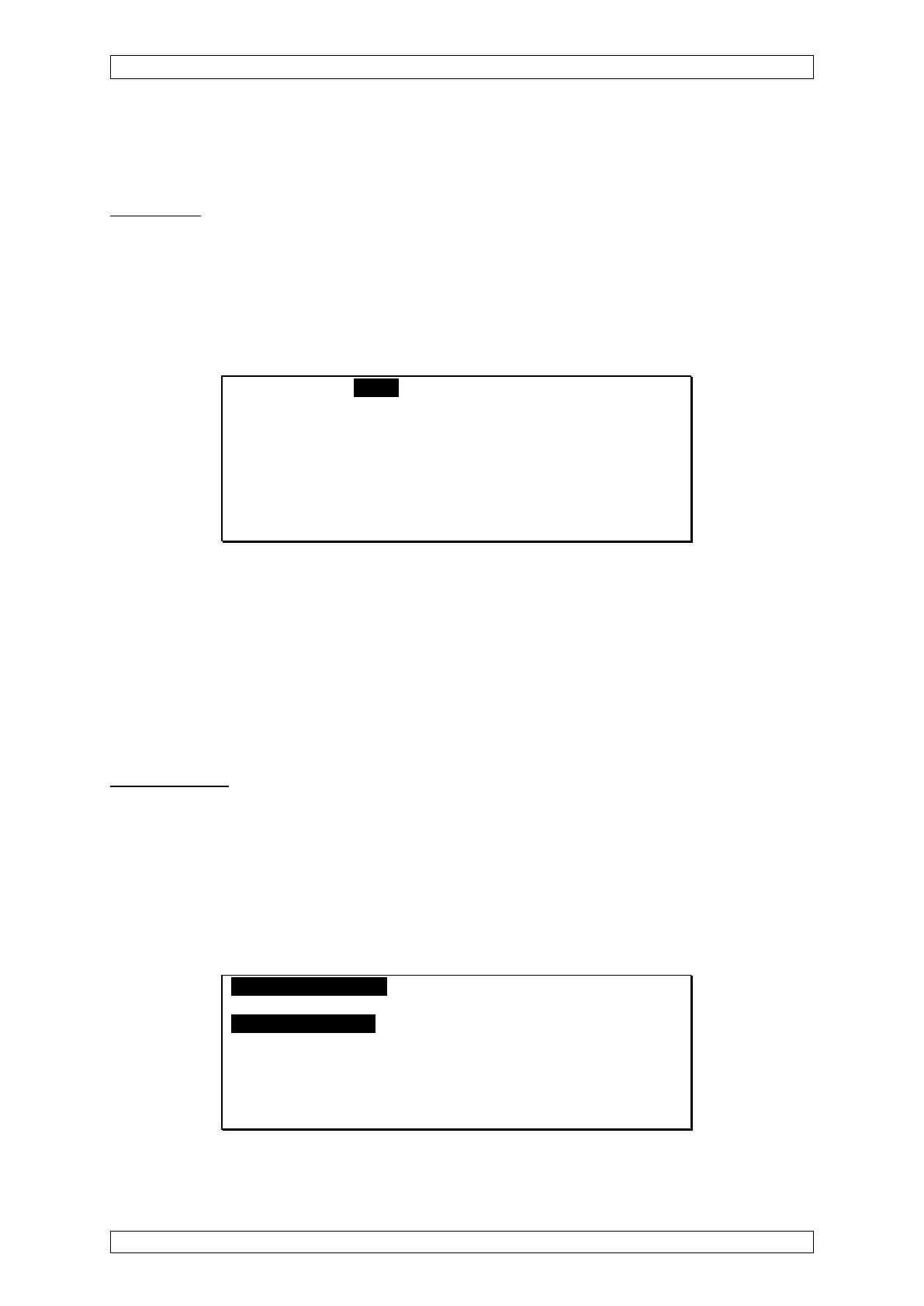
LED display
This display shows the status values of the inputs as LED’s. Each LED column has the
corresponding input number under it.
{: Off (not inhibited, no alarm, no failure)
: On (inhibited, alarm, failure)
If an input is not yet configured no LEDs are displayed in that column.
List Bars LEDs Menu
Inhibit. { { { { { {
4th Al. { { { { { { { {
3rd Al. { { { { { { { {
2nd Al. { { { { { { { {
1st Al. { { { { { { { {
Failure { { { { { { {
1 2 3 4 5 6 7 8
Figure 4-5: Display as LED Field
Setup
Using the “Setup” menu, the operator can set parameters for inputs and relay outputs, as well
as system parameters. The menu includes three menu items:
• Measure point
• Relay output
• System
Measure Points
This menu shows all of the parameters that describe an input. Input parameters can be viewed
and changed here.
The Measure Point menu is divided into three submenus:
• Information
• Sensor data
• Alarms
MeasurePoints RelayOutput System Menu A
Measure Point No.: 1 Inhibit [ ]
[Information] [Sensor Data] [Alarms]
Tag: Q-123
Marking: SP-05
Sensor Ser. Nr.: 115
Install Area: Feld 14
[OK] [Cancel] [Clear]
Figure 4-6: Measure Point Setup menu