REV 0, June 2005Page 138
Operation Manual SUPREMA
5. Installation
Maximum Switching Voltage 400 VAC
300 VDC
Maximum Switching Power, ac: 1500 VA
Nominal Current 3 ADC
Maximum Switching Power, dc: 24 VDC/3 A
(from the load limit curve) 50 VDC/0.3 A
100 VDC/0.1 A
5.7 Connection of the Relay Outputs
The function of the individual relay modules is described in detail in section 3.6.4 Description of
the Modules/Relay Outputs. Depending on the application, the following relay modules can be
used:
• MRO-8 module 8 common alarm relays on the rack
· MRC-TS module connection of 5 relay modules (MRO-8-TS modules),
installed on mounting rail
• MRO-8-TS module 8 relays, installed on mounting rail
• MRO-16-TS module 16 relays, redundant design
(see section 10
Redundant Systems), installed on mounting rail.
The relay modules are controlled by the MGO module, which has 40 switching outputs available
per module. The first 8 switching outputs of the first MGO module in the system are permanently
assigned to the common alarms, whereas the other outputs can be configured freely
(see
section Configuration of the Relay Driver Outputs).
In addition, a system failure relay is available on the MIB module, which is controlled in the
event of a system failure (SYSTEM FAIL, LED is lightened).
The following table provides information on the contact load capacity of MRO modules:
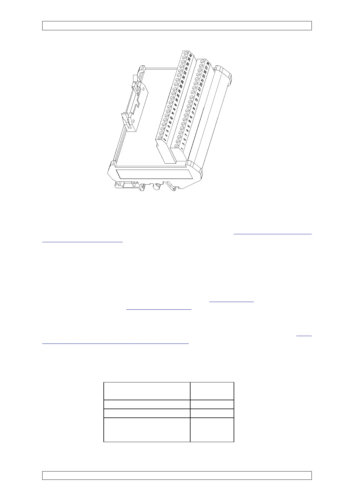
Figure 5-31: MGT-40-TS Module
Table 5-23: MRO-Module, Contact Load Capacity