REV 0, June 2005 Page 121
Operation Manual SUPREMA
5. Installation
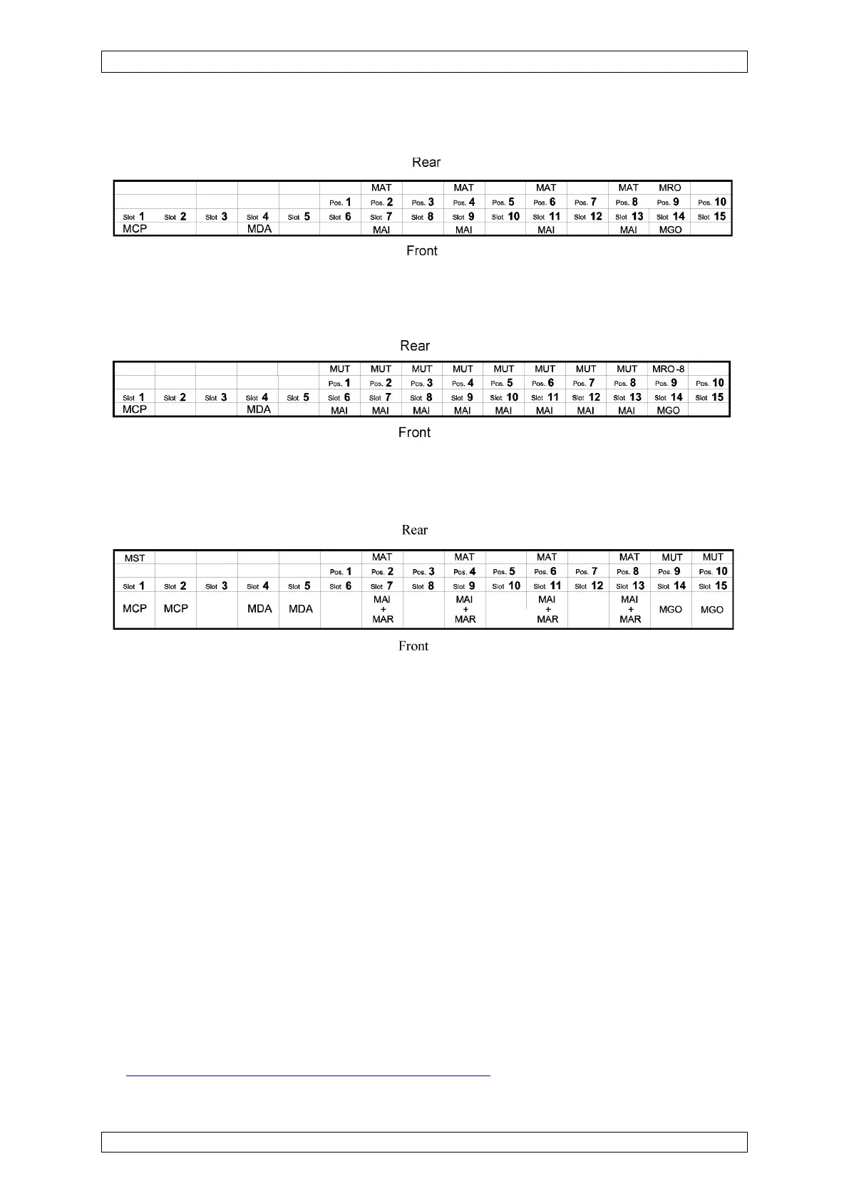
Standard System with 32 Inputs/8 Common Alarm Re
Figure 5-25: Configuration example 2
Standard System with 64 Inputs/8 Common Alarm Relays
Figure 5-26: Configuration example 3
Standard System with 32 Measurement Sites, Redundant Design
Figure 5-27: Configuration example 4
5.5 Systems Consisting of Several Racks
5.5.1 Systems with Central Recording of Measuring Values
In systems with several racks, which are not isolated from each other, the following points
should be kept in mind:
• Each rack must have a guaranteed voltage supply. The GND-connectors of all racks
must be interconnected.
• When the central unit respectively the satellites consist of several racks, note that in
each rack-group the GND-connectors must be interconnected.
• The racks must be connected to each other by a CAN bus.
• The racks are connected by way of the MST module cards on the rear with ready-made
CAN bus cables.
• For a “multi-rack” system, contacts 1 and 2 (CAN-A, CAN-B) of the DIL switch on the MIB
module in the last rack – i.e., the one where the CAN bus ends – should be closed. All
DIL switch contacts 1 and 2 (CAN-A, CAN-B) on the tracks in between must be open
(see section 5.3.1 Configuration of the MIB Module).