REV 0, June 2005Page 122
Operation Manual SUPREMA
5. Installation
• The setting of the CAN bus bit rate must be the same for all racks and should correspond
to the standard settings defined for the total number of inputs in question
(see section
5.3.1 Configuration of the MIB Module).
• Each rack must have it own CAN node number. The standard setting for the first rack is
111
(see section 5.3.1 Configuration of the MIB Module).
• In the case of non-redundant systems, the standard practice is to use the CAN-A bus
connection; when a redundant system is built, the CAN-B is also connected (see section
10 Redundant Systems).
• A cooling fan must be installed and operated for the warmth removal in the installation
framework if more than 65 measuring points are fitted with MPI modules.
Connection Notes
The MAI Module has been modified to facilitate applying the CAN Bus connections.
Unlike the previous MST module (G status A), the revised version (G status B) has an input and
output for each CAN Bus. For this reason, when connecting several racks via CAN bus, the
CAN Bus T-piece is no longer required. (Art.-No.: 10030080).
In the following, the connection of several racks (BGT) via CAN bus is described for both MST
module variations.
Note: For reason of clarity, only one CAN bus is described, the other CAN buses
are connected the same way.
Signification: St = Plug
B = Socket
(stands for plug connectors at the respective line)
For connections and terminal assignment see
section 5.10 System Ports (MST module).
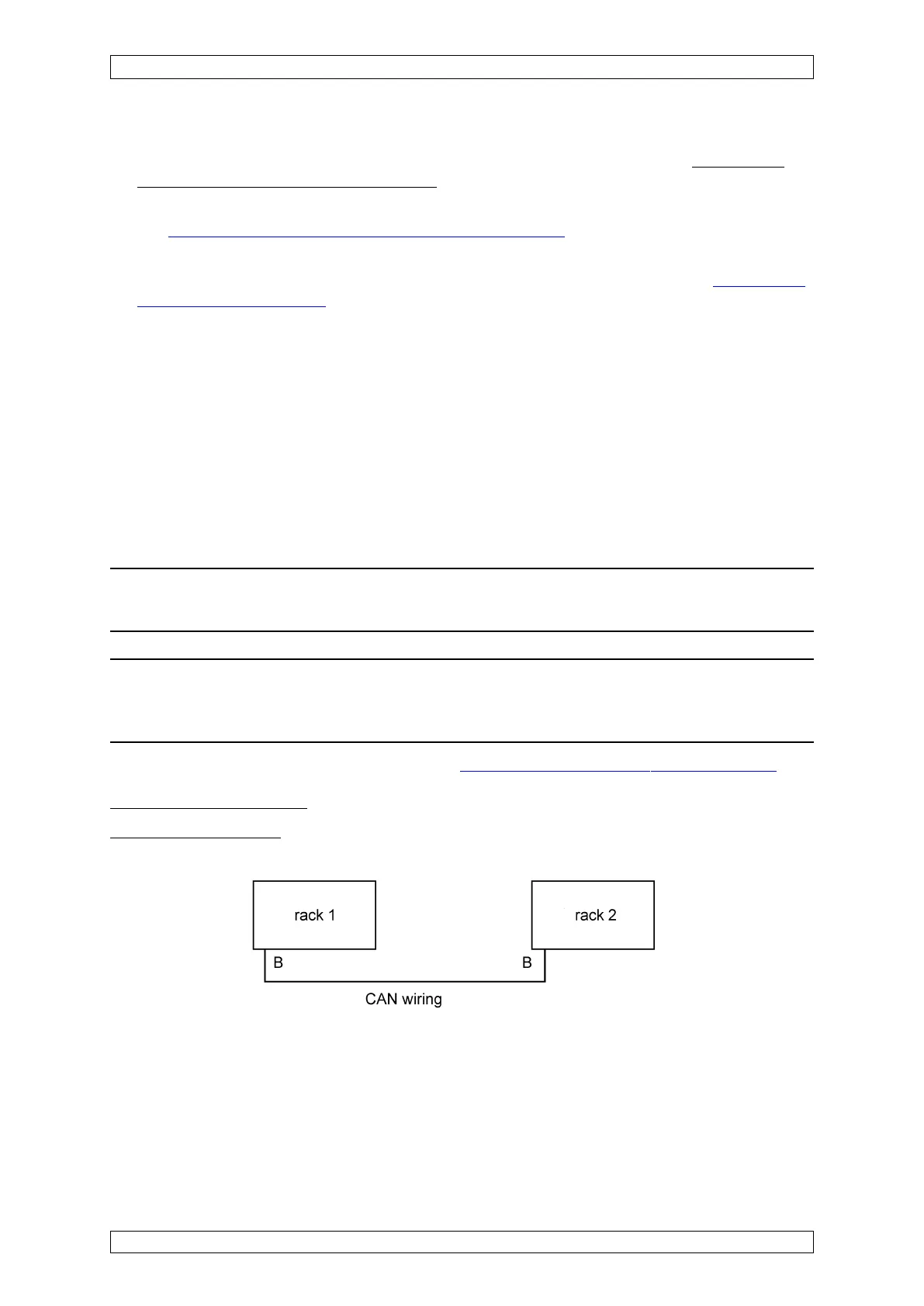
MST Module G Status A:
Connection of 2 racks:
The CAN terminating resistor at Rack 1 is not set, at Rack 2 it is set.