REV 0, June 2005Page 104
Operation Manual SUPREMA
5. Installation
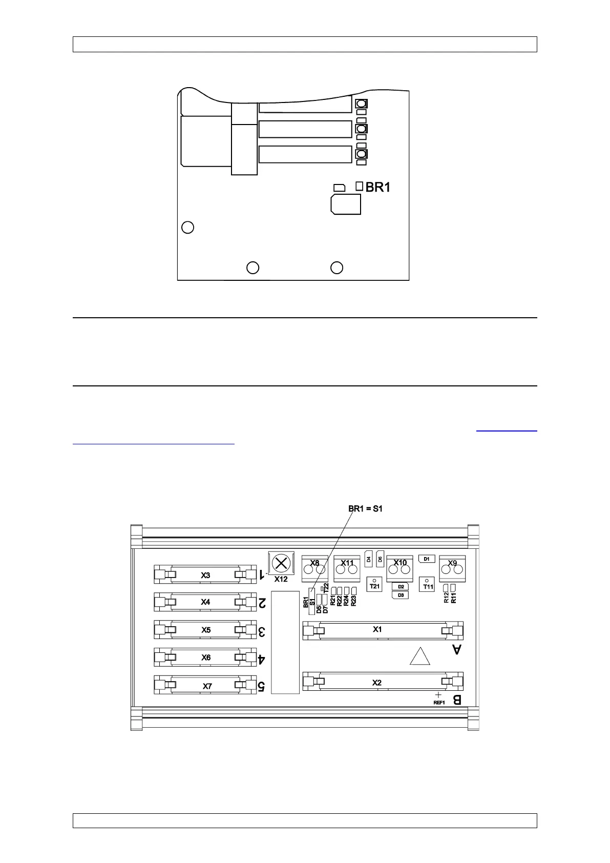
Figure 5-9: Configuration of the MRC-TS module
Figure 5-8: Configuration of the MRO-8 module
Attention: Because the common alarms are normally and this is fixed in the
system and cannot be changed, solder bridge BR1 should never be closed under
any circumstances (unless an alarm is to be triggered when the relays are
inhibited).
5.3.7 Configuration of the MRC-TS Module
A solder bridge (BR1), which is used to determine the function of the relay inhibit (see section
5.7.2 Additional Relay Outputs) for the connected relay modules, is provided on the module:
Solder bridge BR1 = OPEN = relays are energised when the relay inhibit is turned on
Solder bridge BR1 = CLOSED = relays are de-energised when the relay inhibit is turned on