REV 0, June 2005Page 50
Operation Manual SUPREMA
4. Operation of the System
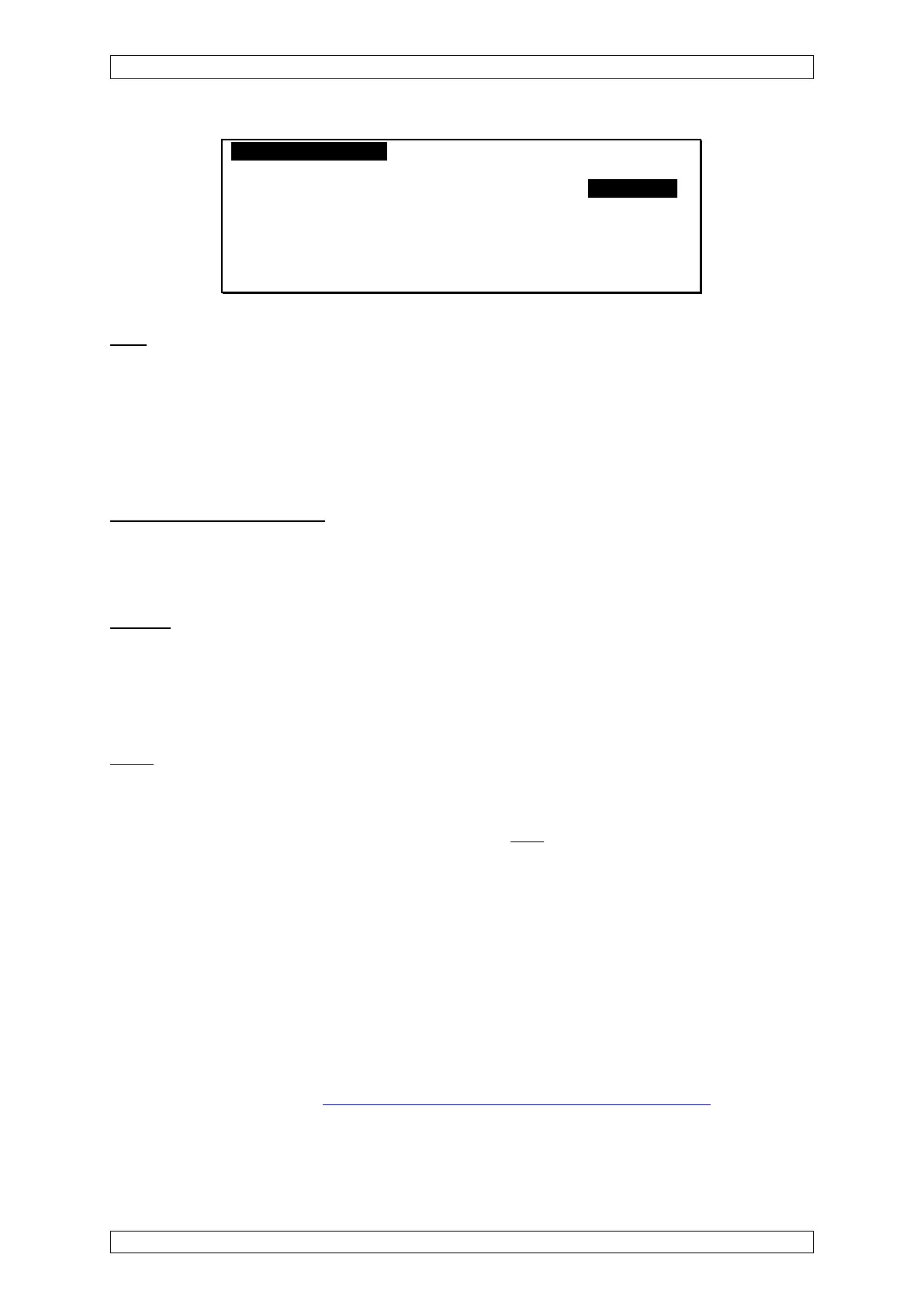
MeassurePoints RelayOutputs System Menu A
Measure Point No.: 1 Inhibit [ ]
[
Information] [Sensor Data] [Alarms]
Upper Latched Limit Relay
1st Al.: [X] [X] 20.00 % LEL ---
2nd Al.: [X] [X] 30.00 % LEL ---
3rd Al.: [X] [X] 40.00 % LEL ---
4th Al.: [ ] [ ] 50.00 % LEL ---
Figure 4-9: “Alarms” submenu
Limit
Field type: decimal number
A limit value can be set here for each alarm at the selected input to trigger on either a rising or
falling input signal.
In this field, it is also possible to deactivate an alarm. Press the Íkey until only zeros are
displayed in the field. If the Ðkey is now pressed, the alarm is deactivated, which is indicated
by the contents of the field being deleted.
Upper (Rising/Falling Alarm)
Field type: Check box
For each alarm at the selected input, set whether the alarm will trip when the signal is rising or
falling. If this check box is enabled it is a rising alarm, if not checked, it is a falling alarm.
Latched
Field type: Check box
The alarm is latching if the check box is enabled, if not, it is non-latching.
This feature has an effect on the behaviour of the MDO front panel LED’s, what is shown in the
“Measure“ menu, and on the relay outputs assigned to an alarm.
Relay
Field type: Selection
These fields contain a list of available relay outputs. Set relay outputs, that will be used, for the
individual alarms at the selected input. Link to this
after selecting a relay output in a relay
output assignment menu.
Relay output assignment menu
This menu is not a submenu of the Measure Point menu, but rather an independent menu that
can only be reached from the Measure Point menu.
It is used primarily to assign relay outputs that will be used if there is an alarm, for the individual
alarms at the input selected in the Measure Point menu.
In addition, this menu also provides the same function as the “RelayOutput” menu.
The top three rows of the menu cannot be accessed here, and are intended only for orientation.
The behaviour of a relay output depends on its parameter settings and the settings of the
appropriate measure points
(see section 6.4.2 Behaviour of the Relay Outputs).