REV 0, June 2005 Page 141
Operation Manual SUPREMA
5. Installation
5.7.2 Additional Relay Outputs
If more relay outputs are required, MRO-8-TS modules are used together with the MRC-TS
module (mounting rail installation). Remember that the first 8 switching outputs of the first
MGO module card in the system are permanently assigned to the common alarms. Thus the
first MRO-8-TS module which is connected by way of the MRC-TS module to the first MGO
module card in the system is always assigned to the 8 common alarms. The connection of the
MRO-16-TS module provided for redundant systems is described in
section 10 Redundant
Systems.
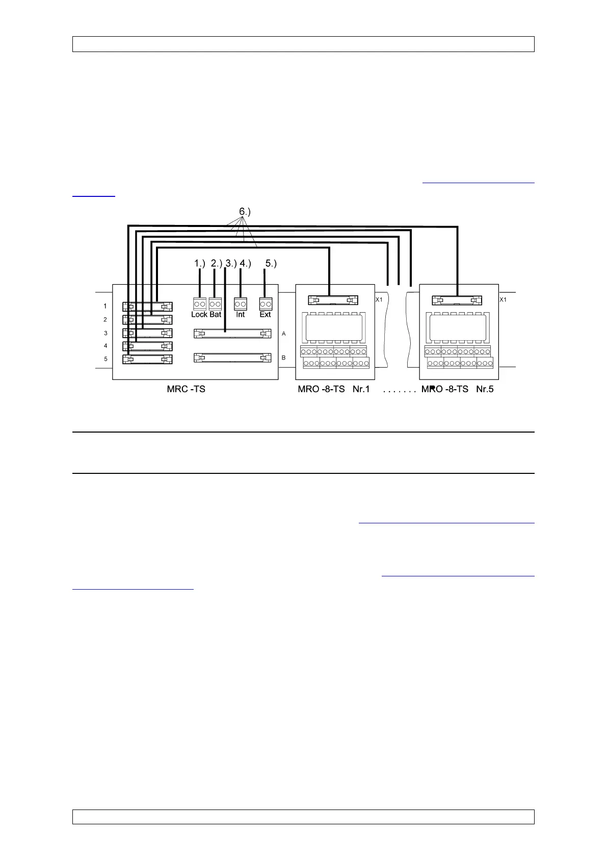
Figure 5-33: Connection diagram of the MRC-TS and MRO-8-TS modules
Attention: The GND of the Bat, Int, and Ext connections of the MRC-TS module
must be connected to the GND of the SUPREMA supply voltage.
The MRC-TS module is connected via connector A by means of a 40-way screened ribbon
cable [3.)] to the MUT module plugged into the rear of the rack. The MUT module establishes
the connection with the MGO module plugged into the rack
(see section 5.4.1 Slot Assignment).
MRO-8-TS modules Nos. 1-5 are connected to the MRC-TS connector 1-5 by means of a 20-
way ribbon cable. In addition, the supply voltage for the relays must be connected to the
terminals Bat [2.)], Int [3.)], and/or Ext [5.)]. As an option, a switch can be connected to the
Inhibit (Lock) terminal [1,)] for the purpose of inhibiting the relays.
(see section 5.3.7 Configuration
of the MRC-TS Module).
MRC-TS Module, Relay Connection Module
This module is used when relay modules for mounting rail installation remote from the rack are
used. Up to 5 TS-relay modules (MRO-8-TS) are connected by way of an MRC-TS module. It
is to this module that the relay power supply and the ribbon cable required for the control of the
relays by the MGO module card are connected. The MGO module is connected to the MRC-
TS-Module with a 40-way ribbon cable and a rack mounted MUT module.
The power supply to the relays must be provided by appropriate connections on the MRC-TS
module. Also note the following points:
• The power supply concept of the MRC-TS module must agree with that of the rack
(assignment of the External/Internal/Battery terminals must agree).
• When different voltage supplies are used for the MRC-TS module and the associated
rack, the GND terminals must be connected together, otherwise the relays will not switch.