REV 0, June 2005 Page 119
Operation Manual SUPREMA
5. Installation
• It is extremely important to ensure that the modules plugged into the rear are
compatible with the modules inserted in the front (e.g., the combination of an MAI
module with an MRO-8 module is non-functional).
(see table 5-11: Assignment of the
Connection Modules)
• The modules plugged into the rear must be located at the same slots as the modules
with the associated functions plugged into the front.
Note: A MAT module covers 2 slots; a MRO-8 module covers 3 slots.
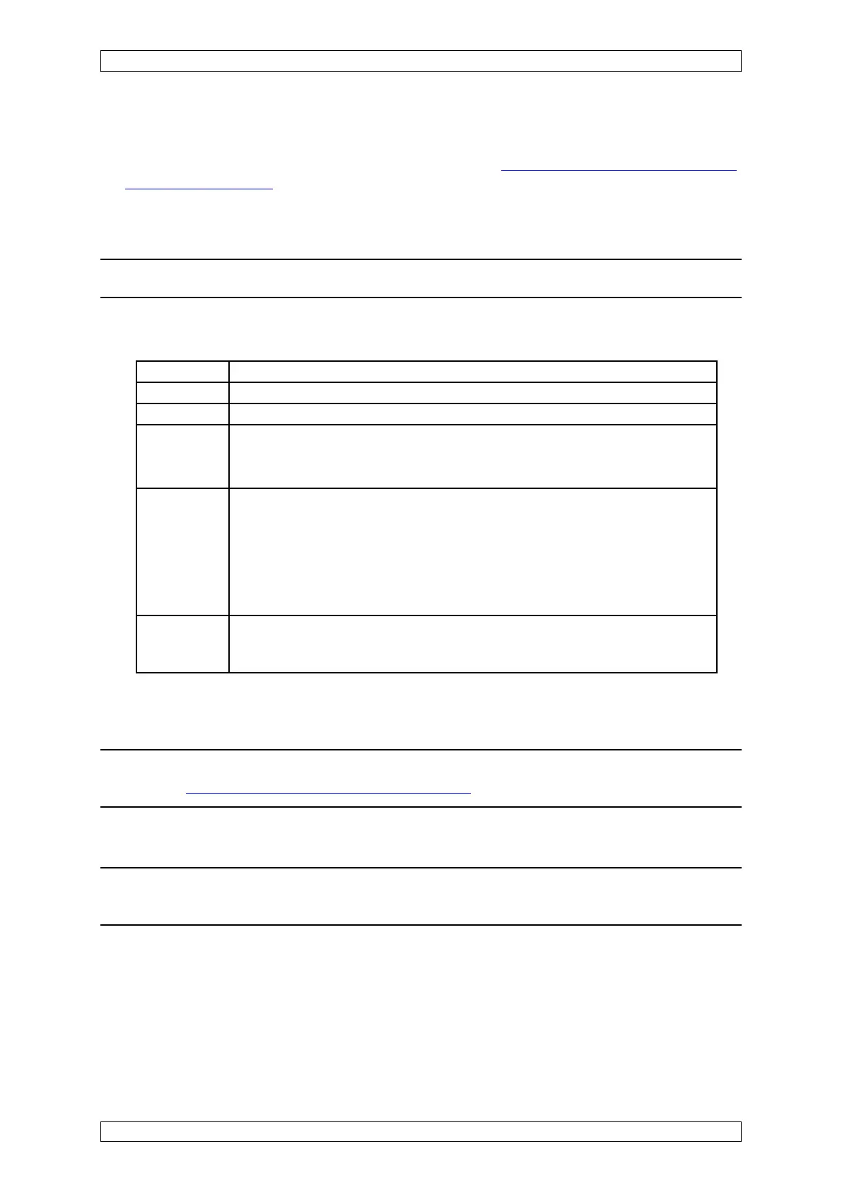
The following combinations of modules installed in the front and in the rear are possible or
required:
Front Rear
MCP module MST module
MDA module ----------
MAI module MAT module (direct connection of sensors)
MUT module (connection to the MAT-TS module or the MGT-40-TS module
for remote connection of sensors)
MGO module MRO-8 module (direct connection of relay outputs)
only POS 9/Slot 14
MUT module (connection to the MRO-8-TS module or the MRO-16-TS
module via the MRC-TS module for remote connection of relay outputs)
MUT module (connection to the MGT-40-TS module for providing driver
outputs for the connection of magnetic valves, etc.)
MAO module MAT module (direct connection of the 4 ... 20 mA outputs)
MUT module (connection to the MAT-TS module or the MGT-40-T module
for remote connection of the 4 ... 20 mA outputs)
Table 5-11: Assignment of the Connection Modules
Note: Further information on the functions of the individual modules can be
found in section 3.6 Description of the Modules.
5.4.3 Maximum Loads
Note: It is extremely important to ensure that the maximum loads are not
exceeded in order to guarantee a reliable operation.
The following load limits must not be exceeded when a SUPREMA system is being configured:
The operating voltage may be from 19.2 VDC to 32 VDC. The values specified below are for an
operating voltage 24 VDC.