REV 0, June 2005Page 118
Operation Manual SUPREMA
5. Installation
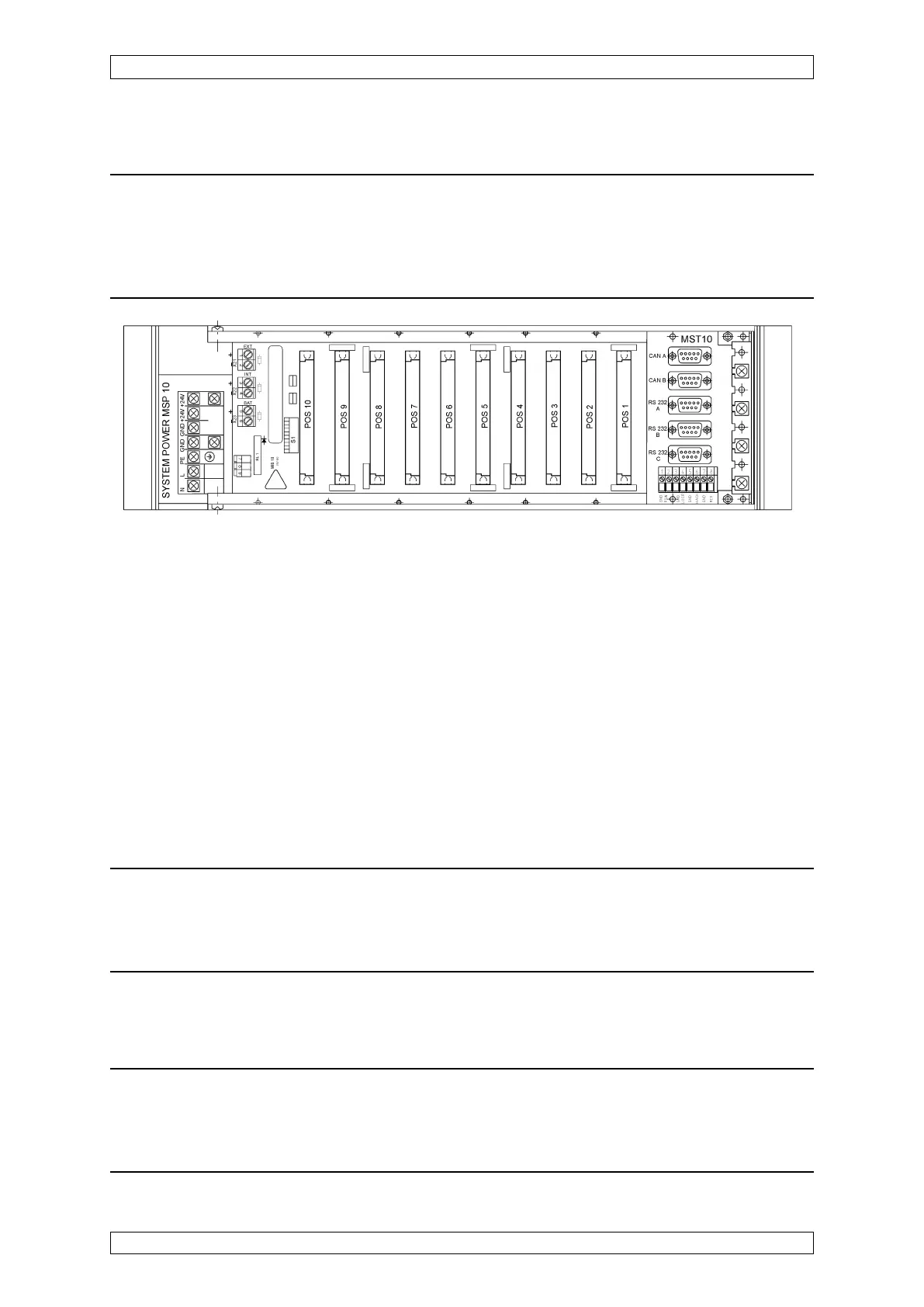
Connection sites on the rear of the rack:
MST: connection site for the MST module only
MXT(Positions 1–10): connection site for:
- MAT module (8 x 5 terminals)
- MUT module (40-way ribbon cable)
- MRO-8 module (Position 9!)
5.4.2 System Requirements
The following requirements must be fulfilled in order to build a functional system:
• Exactly one MCP module and one MDO module are required for a system (up to 8 racks)
(non-redundant design). The MCP module must be properly connected by ribbon cable
to the MDO module mounted in the front panel.
• Exactly one MDA module is required for a rack (non-redundant design) if MAI modules
are also present in the rack.
• The numbering of the measurement channels of the MAI modules is determined by the
selected slot. Channels 1–8 are assigned to slot 6 (POS 1), channels 9–16 to slot 7
(POS 2), etc.
Attention: In the standard design with a MAT module installed in the rack, the
first MAI module must be inserted into slot 7 (POS 2), the 2
nd
MAI module into
slot 9 (POS 4), etc. Thus the measurement channel numbers obtained are: 1
st
MAI module (POS 2): 9-16. 2
nd
MAI module (POS 4): 25-32, etc.
• The system automatically assigns the measurement channels numbers 18 and the
associated measurement values to the first inserted MAO module card (and the
measurement channel numbers 9–16 to the second MAO module card, etc.).
Attention: Because, in the standard design with a MAT module inserted in the
rack, this module is in slot 7 (POS 2/measurement channel numbers 9-16), two
MAO module cards must be inserted in order that the measurement values of
measurement channels 9-16 can be transmitted as 4 ... 20 mA output signals.
Figure 5-23: Rear of the Rack