REV 0, June 2005 Page 223
Operation Manual SUPREMA
10. Redundant Systems
10.3.5 Installation MGO Module
Before plugging in modules, the SUPREMA system must be voltage-free.
The module must be configured via jumper plugs for the CAN B bus.
CAN-A BR11 + BR13 = CLOSED & BR12 + BR14 = OPEN
CAN-B BR11 + BR13 = OPEN & BR12 + BR14 = CLOSED
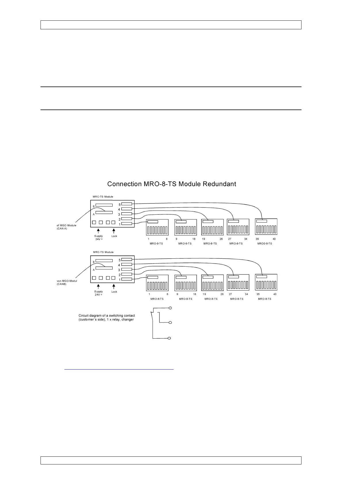
10.3.6 Connection MRO10-8-TS Module
On redundant systems, the outputs of 2 MGO modules must always be connected (channel
A + B).
The 40 driver outputs of the MGO modules are connected to the MRC-TS modules of Plug A
using a 40-way ribbon cable via MUT modules at the rear of the rack. Plug B is only used if
MRO-16-TS Modules are connected. Using a 20-way ribbon cable each of the plugs 1–5 are
connected to the 8 driver outputs of the MGO module to up to 5 MRO-8-TS modules.
Figure 10-3: Connection MRO-8-TS Redundant Module
The terminal connections and the relay assignment of the MRO-8-TS module are described in
detail in
section 5.7.2 Additional Relay Outputs.
10.3.7 Connection MRO-16-TS Module
If the system is redundant, the outputs of 2 MGO modules must always be evaluated (channel
A + B). The connection of up to 5 MRO-16-TS modules (40 outputs) is achieved via 1 MRC-TS
module. Using 20-way ribbon cables, each of the plugs, 1–5, are connected via the 8 driver
outputs (channel A + B) of the MGO modules to up to 5 MRO-16-TS modules.