REV 0, June 2005 Page 169
Operation Manual SUPREMA
6. Startup
6.3.3 MAI Module - Instrument Status “A” and “B”
6.3.3.1 Adjust the Sensor Current
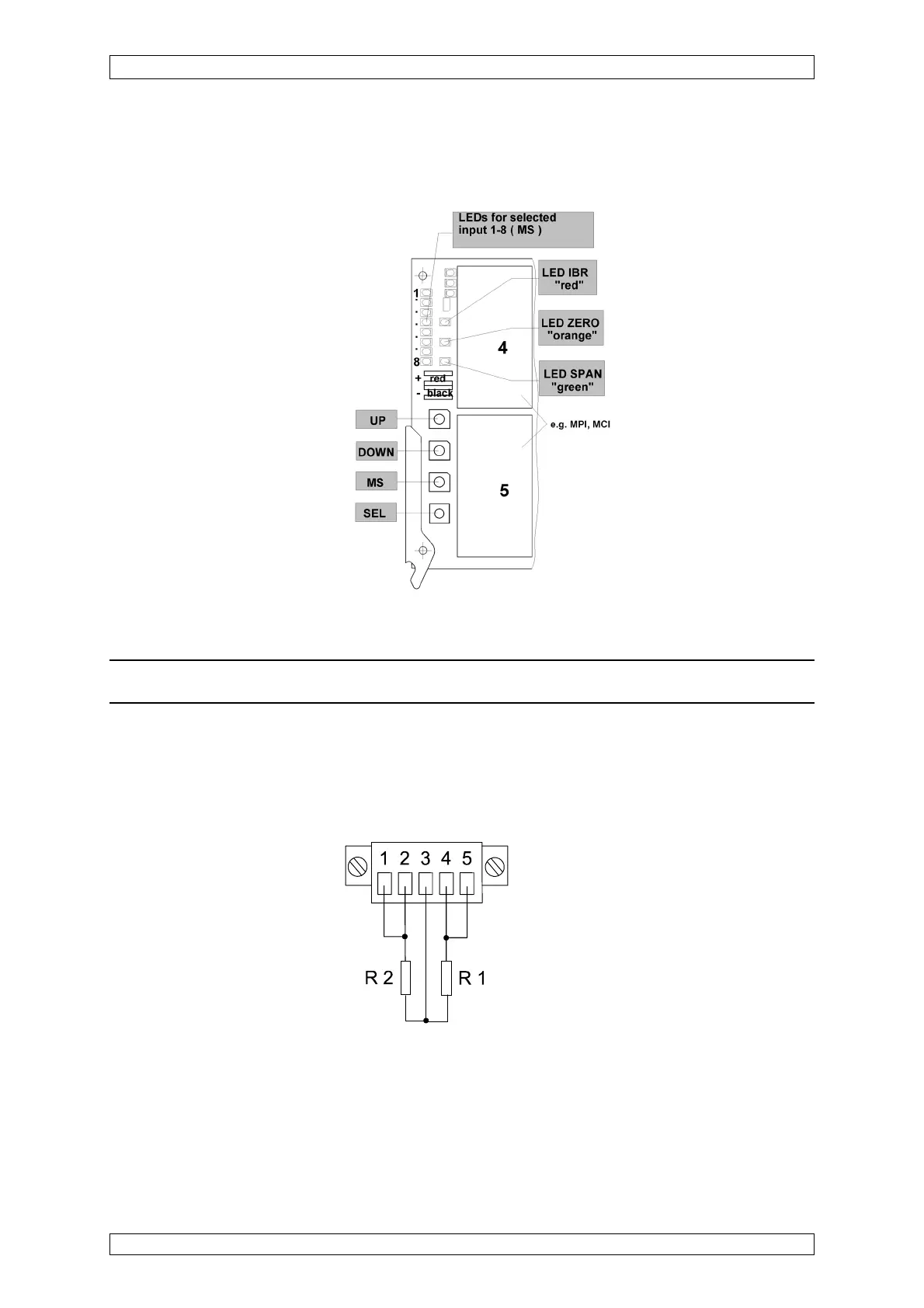
Figure 6-8: Display and operating elements of the MAI module - Instrument Status “A” and “B”
Attention: Do not connect the sensor yet!
To prevent accidental damage to the sensor or even its destruction by excessive bridge current,
an equivalent sensor circuit is used to adjust the sensor current. The MSA equivalent sensor
module appropriate for the type of sensor can be used for this purpose. If this is not available,
a MAT connector plug, wire resistors, and wire bridges can be used to build an equivalent
sensor as shown in figure 1-9.
R1=R2=3,9
Ω
Figure 6-9: Equivalent sensor circuit for the MPI-WT100/MPI-WT10 module