REV 0, June 2005 Page 127
Operation Manual SUPREMA
5. Installation
For parameter setting, a serial interface (DSUB plug connector X100) is provided. The CAN
Bridge parameters can be set using a terminal program (e.g. Hyper Terminal for Windows).Details
of this process are described below.
The code switches SW211 and SW210 of the CAN Bridge are only for internal service purposes
and must always be in position 0. When both LED‘s (1 and 2) are on the status is ‘good‘. If there
is a failure at one of the two CAN buses, the corresponding LED will flash, LED 1 for NET 1,
and LED 2 for NET 0.
For the correct function of the SUPREMA CAN bridge, some points must be considered:
a) Baud rate setting at the Central Rack (depends on the number of measuring points)
b) Baud rate setting at the satellite rack (depends on the distance of the satellite)
c) Rack number (Dip switch at the MIB module)
d) Components of the Satellite racks (Plug positions of the MDA, MGO, MAO, MAI modules)
Note: 32 filters max. may be set, i.e., in a satellite, 9 MGO/MAO modules max. can
be integrated. The number of MDA/MAI modules per rack is not limited.
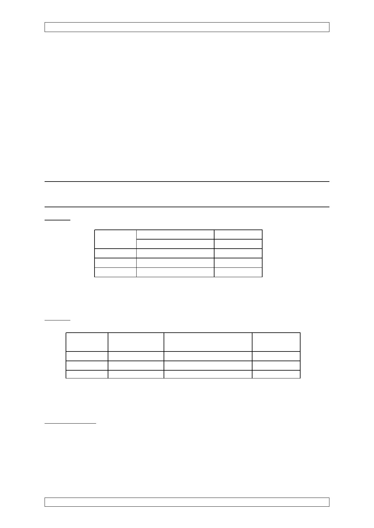
As to a):
Measuring 5 Bit rate setting in kB/s Bridge
points
Simplex/Duplex
command
1 - 64 125 B0:6
65 - 128 250 B0:4
129 - 256 250 B0:4
Measuring Distance in m Bit rate setting in kB/s Bridge
points command
1 - 64 0 - 800 50 B1:9
65 - 128 0 - 400 125 B1:6
129 - 256 0 - 200 250 B1:4
Table 5-15: Baud rate at the Central Rack
As to b):
Table 5-16: Baud rate at the Satellite Rack
As to (c) and (d):
The CAN identifier for the CAN Bridge filter function must be calculated, see the following
section. After calculation, the results must be transformed to hexadecimal numbers.