REV 0, June 2005Page 120
Operation Manual SUPREMA
5. Installation
Table 5-12: System Configuration/Maximum Loads
Table 5-13: MGO Module/Maximum Loads
Maximum output current of an input 400 mA
Maximum output power for an input (Sensor and cable) 5 W
Maximum output power for a MAI module 40 W
Maximum output power for 8 MAI modules 320 W
Maximum input power for 8 MAI modules 400 W
Maximum input power for a MIB module (for a rack) 480 W
Maximum current load for a MIB module 20 A
Maximum current load MIB module/GND terminal 32 A
(MAI module and MGO module currents)
Maximum output current for a MSP module (Rack - power pack) 6.5 A
Maximum output power for a MSP module (Rack - power pack) 150 W
Nominal current of a driver output 0.3 A
Maximum current of a driver output 1.0 A
Maximum current for 8 driver outputs (a MGO module has each 5 driver 4.0 A(8 x 0.5 A)
Ics with each 8 driver outputs)
Maximum current total of all current loads of a MGO module (one MGO 12 A (40 x 0.3 A
module is disposing of 40 driver outputs)
When setting the number of modules allowable per rack, the following factors of influence have
to be observed:
• The power of the sensors to be connected including the losses resulting from the cable
lengths (MAI module/ MIB module).
• The currents of the modules connected to the relay driver outputs (MGO module/ MIB
module: GND terminal).
• The power requirement of the system modules
(see table 5-36: Power Requirements of
the System Modules).
• The power available from the supply voltage.
For further details, see the tables in
section 5.11 Connection of the System Power Supply and
section 11 Technical Data and the operation and maintenance manuals of the sensors to be
connected.
Note: A cooling fan must be installed and operated to prevent overheating in the
installation framework if more than 65 measuring points are fitted with MPI modules.
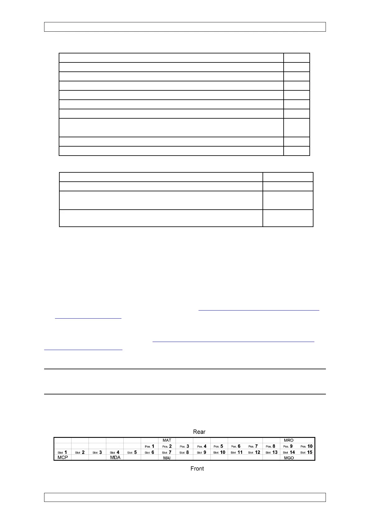
5.4.4 Configuration Examples
Standard System with 8 Inputs/8 Common Alarm Relays
Figure 5-24: Configuration example 1