REV 0, June 2005 Page 215
Operation Manual SUPREMA
9. Connection of Peripherals
• Operation manual ComPro Project and Service program DOS Program
• Protocol manual CANopen Slave
Physical MOD-Bus Interface:
• RS 232C* (Point to Point Interface, 19200 Baud max.)
• RS 485 (2 [3] wire Bus Interface, 19200 Baud max.)
• RS 422 (4 [5] wire Bus Interface, 19200 Baud max.)
All interfaces are connected by a 9-pin D-SUB plug connector. The plug pin assignment and
the interface parameters can be seen in the gateway device manual PKV 30-COS Protocol
converter for CANopen Slave.
Data format MOD Bus RTU Standard:
There are 3 different modes which can be used.
• Mode 1 contains the measuring value in INT16 , dimension and measuring range of the
individual measuring points
• Mode 2* only contains the measuring values in INT16 of the individual measuring points.
• Mode 3 contains the measuring value as a decimal number, measuring point No.,
measuring point status, dimension and measuring range.
* Basic setting (See Bridge manual Transfer CANopen Slave to MSA AUER at the PKV30-COS)
Parameter setting is made by the comPro program enclosed on a floppy disc. (See
operation manual “Project planning and diagnostic program” DOS program.)
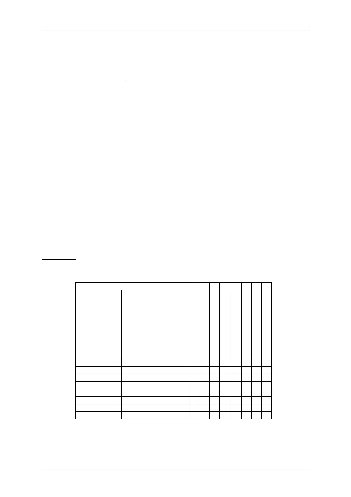
Truth Table
For the status register from address 10001 on, the following truth table (10001–10008) is valid
for measure point MS 1:
Event
Memory address Data value
1st alarm
2nd alarm
3rd alarm
4th alarm
Calibration
Signal failure
Inhibited
Measure range exceeded
10001 1st alarm 1 1 1 1 0 0 0 1
10002 2nd alarm 0 1 1 1 0 0 0 1
10003 3rd alarm 0 0 1 1 0 0 0 1
10004 4th alarm 0 0 0 1 0 0 0 1
10005 Calibration 0 0 0 0 1 0 0 0
10006 Signal failure 0 0 0 0 1 1 1 0
10007 Inhibited 0 0 0 0 0 0 1 0
10008 Measure range exceeded 0 0 0 0 0 0 0 1
For measure points MS 2– 56 see above as for measure point MS 1.