REV 0, June 2005Page 234
Operation Manual SUPREMA
10. Redundant Systems
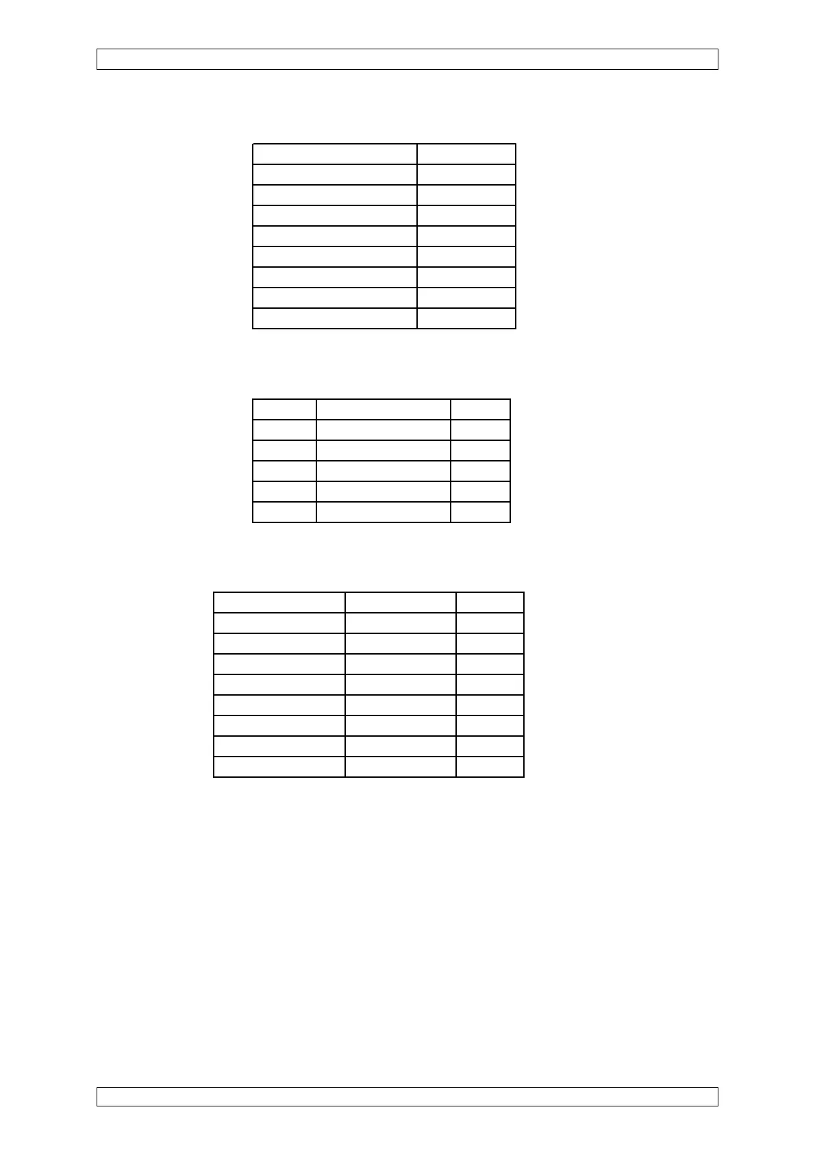
Front Panel Display
1.LED SYSTEM POWER ON
2. LED SYSTEM FAIL OFF
3. LED SYSTEM INHIBIT OFF
4. LED SIGNAL 1 AL OFF
5. LED SIGNAL 2 AL OFF
6. LED SIGNAL 3 AL OFF
7. LED SIGNAL 4 AL OFF
8. LED SIGNAL FAIL OFF
9. LCD Display Display Listing
Displays of the Module Cards
All CAN-BUS Module cards have the following LED displays:
LED Function Require
LED 1 GN EXT = ON OFF
LED 2 GN INT = ON ON*
LED 3 GN BAT = ON OFF
LED 4 RT CAN-BUS Failure OFF
LED 5 GN CAN-BUS in Operation ON
*= Rack operation via INT terminals
Displays of the MAI Modules
LED Function Required
LED 1-8 MS 1-8 = ON OFF
LED EXT EXT = ON OFF
LED INT INT = ON ON*
LED BAT BAT = ON OFF
LED IBR IBR ON SOCKETS OFF
LED ZER UY ON SOCKETS OFF
LED SIG UA ON SOCKETS OFF
LED of connector strip Signal Request FLASHING
*= Rack operation via INT terminals
Check of the Signal Processing/Alarming
After a successful startup and setting of the system parameters, a functional check must be
carried out:
• By application of test gas, alarms should to be initiated.
• Test of the switching output functions according to the relay configuration.