REV 0, June 2005 Page 261
Operation Manual SUPREMA
12. Sensor Data Sheets
Open or Short Circuit Fault Indication:
X = Signal failure (FAIL-LED)
XX = Alarm LEDs, Signal exceeded, Signal failure (FAIL-LED)
XXX = only alarms
XXXX = no change of indication
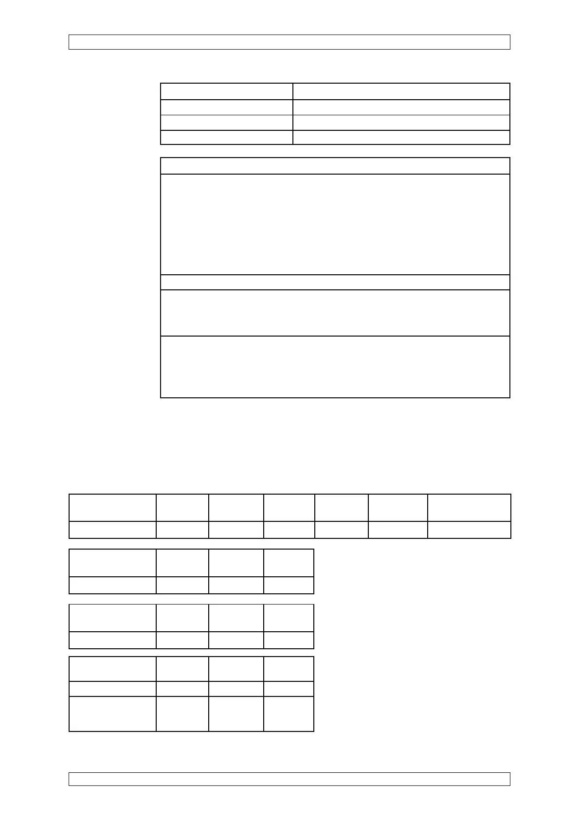
Short-circuit at the Wire Wire Wire
MAT-(TS)-Module -X1/2/-X1/3 -X1/2/-X1/4 -X1/3/-X1/4
Failure indication XX X X
Open-circuit at Wire Wire Wire
max. cable length -X1/2 -X1/3 -X1/4
Failure indication X X X
Open-circuit at the Wire Wire Wire Bridge Bridge Disconnect plug
MAT-(TS)-Module -X1/2 -X1/3 -X1/4 -X1/1 /-X1/2 -X1/4 /-X1/5 of MAT-(TS)
Failure indication X X X XX X X
Startup: Presetting required —> before first calibration and when changing sensor
Presetting: Connect digital voltmeter to MAI card jacks.
Bridge current setting —> 270 mA resp. 300 mA (for CH
4
)
Zero adjustment by zero gas —> Zero setting to Ua = 400 ... 450 mV
Sensitivity adjustment with measuring gas —> Measuring range level
Ua = 1950 ... 2100 mV
or by means of the value of the existing gas concentration according to:
Ua (mV) = C (Span gas concentration in % of measuring range) / 100
*
1600 + 400
Warm-up period: ≤ 60 s according to EN 50054, 15 minutes for presetting, 2 hours for calibration
Function test: Span gas application via: PK10 with 1.0 l/min
or PV10 with 1.0 l/min
or splashwater-proof housing with 1 l/min
Calibration: Calibration procedure according to SUPREMA operation manual
For measuring components allowed, measuring ranges, lower alarm levels and
conditions for calibration see list of components. (Order No.: D0792420)
Possible other measuring components and measuring ranges on request.
Short-circuit at Wire Wire Wire
max. cable length -X1/2/-X1/3 -X1/2/-X1/4 -X1/3/-X1/4
Failure indication XX XXXX X
At conductor resis- XX X X
tance 0 ... 1.7 Ohm
per lead
Pressure 950 ... 1100 hPa
Weight approx. 430 g
Dimensions W x D x H 80 mm x 55 mm x 125 mm
Housing material Die-cast housing Polyamide 6