■
Example of processing
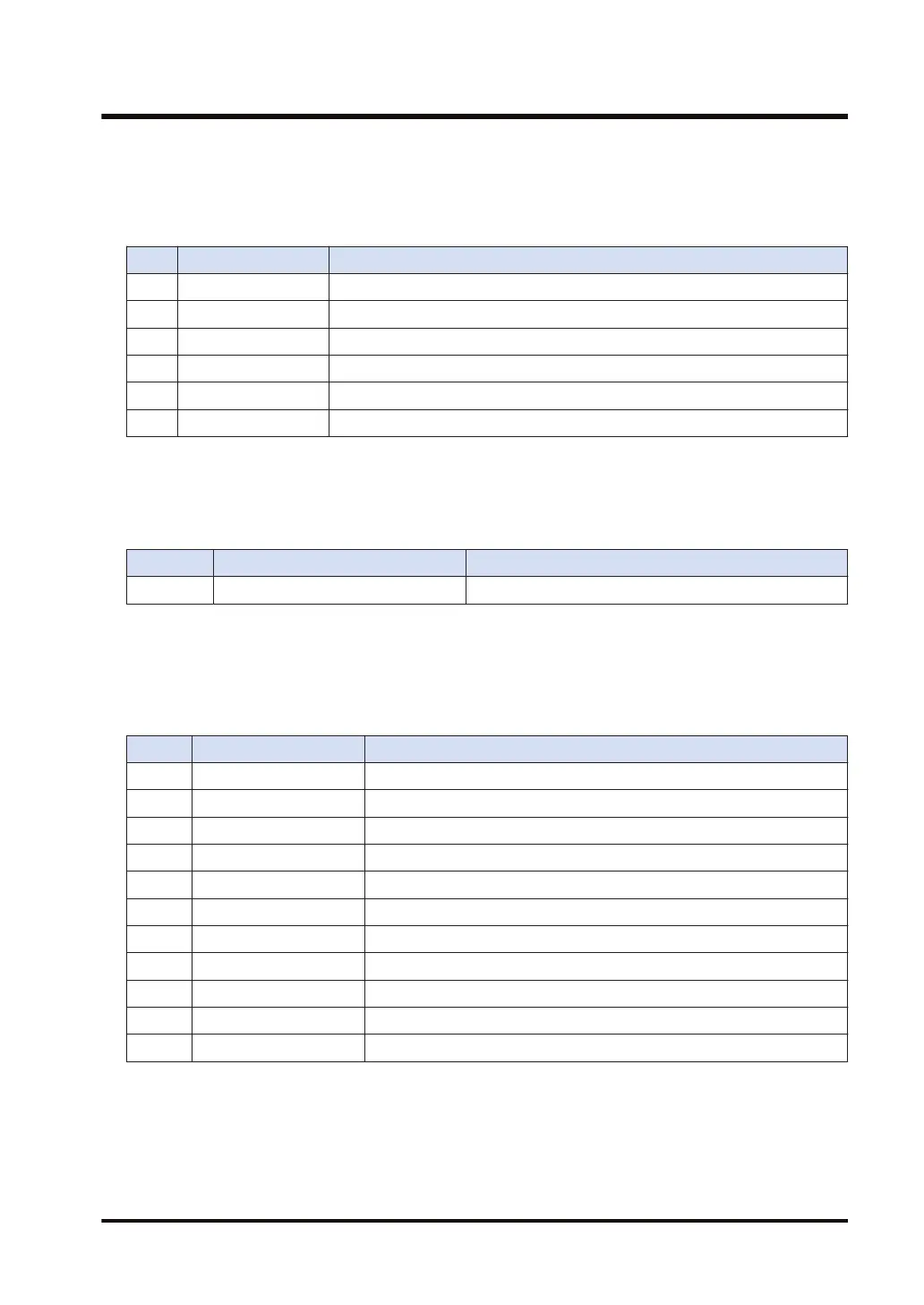
Example 1) When specifying the reading of EtherNet/IP communication state
[S1]... "EIP" [S2]... "ALL" [D]...DT20
Value
DT20 U15 Maximum registration node number
DT21 0111 1111 1111 1111 Cyclic communication registration node table (Node nos. 1 to 16)
DT22 0111 1000 1011 1111 Cyclic communication normal node table (Node nos. 1 to 16)
DT23 0000 0111 1010 0000 Cyclic communication stop node table (Node nos. 1 to 16)
DT24 0000 0000 0100 0000 Cyclic communication abnormal node table (Node nos. 1 to 16)
DT25 0000 0000 0000 1111 RUN/IDLE bit monitor (PLC standby flag) (Node nos. 1 to 16)
Example 2) When specifying the reading of EtherNet/IP communication state
When the maximum registered node number is "0", only the value of [D] is updated and the
values after [D+1] are not updated.
[S1]... "EIP" [S2]... "ALL" [D]...DT20
Value
DT20 0 Maximum registration node number
Example 3) When specifying the reading of cyclic communication registration node
table
When setting "ALL+2" for [S2], the information for 32 (=2x16) nodes (node numbers 1 to 32) is
read.
[S1]... "EIP" [S2]... "ALL+2" [D]...DT20
Value
DT20 15 Maximum registration node number
DT21 1st word Cyclic communication registration node table (Node nos. 1 to 16)
DT22 2nd word Cyclic communication registration node table (Node nos.17 to 32)
DT23 1st word Cyclic communication normal node table (Node nos. 1 to 16)
DT24 2nd word Cyclic communication normal node table (Node nos. 17 to 32)
DT25 1st word Cyclic communication stop node table (Node nos. 1 to 16)
DT26 2nd word Cyclic communication stop node table (Node nos. 17 to 32)
DT27 1st word Cyclic communication abnormal node table (Node nos. 1 to 16)
DT28 2nd word Cyclic communication abnormal node table (Node nos. 17 to 32)
DT29 1st word RUN/IDLE bit monitor (PLC standby flag) (Node nos. 1 to 16)
DT30 2nd word RUN/IDLE bit monitor (PLC standby flag) (Node nos. 1 to 32)
Example 4) When fixing the number of valid words (The communication states of
node numbers 1 to 16 are displayed.)
[S1]... "EIP" [S2]... "ALL+1" [D]...DT20
When setting "ALL+1" for [S2], the information for only one word (node numbers 1 to 16) is read
regardless of the maximum registered node number.
17.28 ETSTAT (Acquiring EtherNet/IP Information)
WUME-FP7CPUPGR-12 17-145

 Loading...


