● Confirm that the master communication clear to send flag is ON for the corresponding
connection, and execute the SEND/RECV instruction. The master communication clear to
send flag will not turn ON until the connection to the partner is established. It is
recommended to specify to "enable the auto open function" in the connection setting of ET-
LAN. Also, the connections can be connected with OPEN instruction.
● The SEND or RECV instruction cannot be executed for the connection for which the master
communication is in progress. Confirm that the master communication sending flag is OFF,
and execute the instructions.
● The SEND or RECV instruction cannot be executed for the connection for which the slave
communication is in progress. (such as performing a data request from a host computer).
● Up to 16 instructions can be executed simultaneously for different COM ports and
connections. (The total of simultaneous usage of SEND, RECV, pGPSEND, GPTRNS, and
pPMSET instructions.)
■
Specification of [S1], [S2], [n], and [D1]
● For the operand [S1], specify hexadecimal data that consists of the source device code and
the upper device address of the partner unit.
Example: When the device code is 3 (internal relay) and the two-digit hexadecimal of the
upper device address is H00, specify H300.
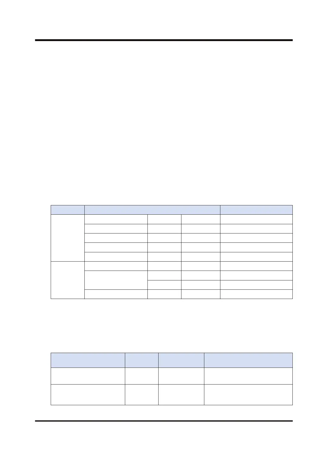
● Specify one of the following values as the "high byte of [S1]" that indicates the device code of
the partner unit.
Unit Device type High byte of [S1]
Bit
Input X Hexadecimal H0
Output Y Hexadecimal H 1
Link relay B Hexadecimal H 2
Internal relay M Decimal H 3
Latch relay L Decimal H 4
Word
Data register D Decimal H 5
File register
R Decimal H 6
ZR Hexadecimal H 7
Link register W Hexadecimal H8
● For the device address of the partner unit, specify six-digit hexadecimal (three-byte) data that
consists of the low byte of [S1] and the value of [S2]. When the device address is in the
range of H0 to H00FFFF, specify "H00" for the low byte of [S1].
● The number of received data [n] is specified in words for the register transfer and in bits for
the bit transfer.
● The transfer method and the number of received data [n] vary according to the device code
on FP7 that is specified by the operand [D1].
Type of FP7 device specified
for [D1]
Transfer
method
Number of
received data[n]
Remark
16-bit device.
WX, WY, WR, WL, DT, LD
Register
transfer
1 to 960
1-bit device.
X, Y, R, L, DT.n, LD.n
Bit transfer 1 to 7168
When the number of receive data is
an odd number, a four-bit dummy
code H0 is added.
17.40 RECV (MC Protocol Master)
WUME-FP7CPUPGR-12 17-203

 Loading...


