■
Execution result code [D2]
Code Description Code Description
H0 Normal end H4 Transmission timeout
H1
The communication port is being used in the
master communication.
H5 Response reception timeout
H2
The communication port is being used in the
slave communication.
H6
Reception error
(Note 1)
H3
The number of master communication
instructions simultaneously used is exceeded.
H7
I/O allocation shortage error
(Note 2)
(Note 1) It occurs when an abnormal telegram is received. When there is a format error in the header of an
individual protocol, the communication discards the received data and a response reception timeout
occurs.
(Note 2) It occurs when the communication control I/O relays corresponding to the communication port (master
communication clear to send flag, master communication send active flag, master communication
send done result relay)are not allocated as I/O words of the CPU unit in the I/O map. It occurs only
when the number of user connections of ET-LAN is expanded and this instruction is executed
specifying the expanded connections.
(Note 3) For details of the execution result codes that may be set if a communication error occurs, refer to "Exit
codes when communication error occurs""P.17-205".
■
Sample program
● An MC protocol command (bulk read) is sent from the LAN port of the CPU unit, and data in
the addresses D000100 to D000101 of an external device is read and stored in the data
registers DT300 to DT301 of FP7.
● After it is confirmed that connection 1 is established in master mode (X90) and no
transmissions are currently being executed for the same port (Y90), the RECV instruction is
started.
● The UNITSEL instruction is used to specify a slot number (LAN port: U100) and the
connection number (U1).
● The RECV instruction is executed with the code (H500) that indicates the device type and
the upper address of the partner unit, the lower address (H64=100), the number of data (U2),
and the storage address (DT300) of FP7.
● It is possible to check if a send error occurs by the sent flag (Y70) when the sending flag
(Y90) turns OFF.
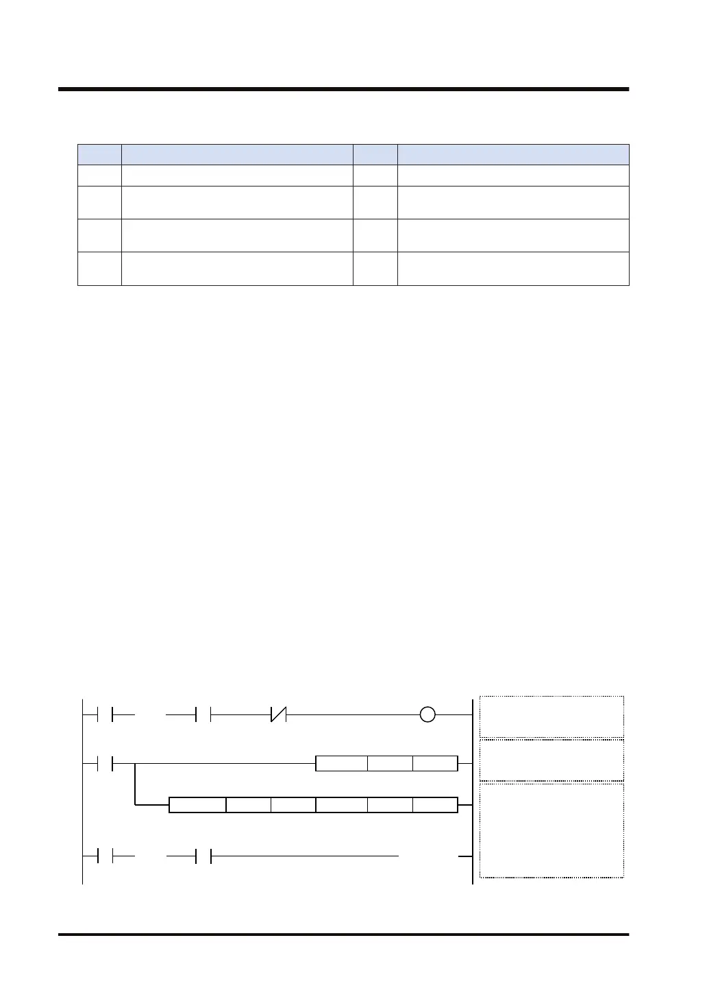
R100
UNITSEL U100 U1
RECV.US DT0U2 DT300H500 H64
RECV
execution relay
Communication port settings
S1: CPU LAN port (U100)
S2: Connection 1 (U1)
RECV execution conditions
Clear to send flag: ON
Send active flag: OFF
RECV instruction execution
S1: MC device type (H5)
MC upper address (H00)
S2: MC lower address (H64=100)
n: Amount of received data (U2)
D2: Data storage location (DT300)
D3: Execution result code (DT0)
Master
communication
clear to send flag
Master
communication
send active flag
( )DF
S1 S2
S1 S2 n D1 D2
Y90 R101
Send result
( )DF/
Send active flag
< >
SET
Send result flag
ON in abnormal state/OFF in normal state
(Note 1) The above program example holds the send result hold relay (R101). Insert a program that resets the
relay after the relay is checked.
17.40 RECV (MC Protocol Master)
17-204 WUME-FP7CPUPGR-12

 Loading...


