■
Processing
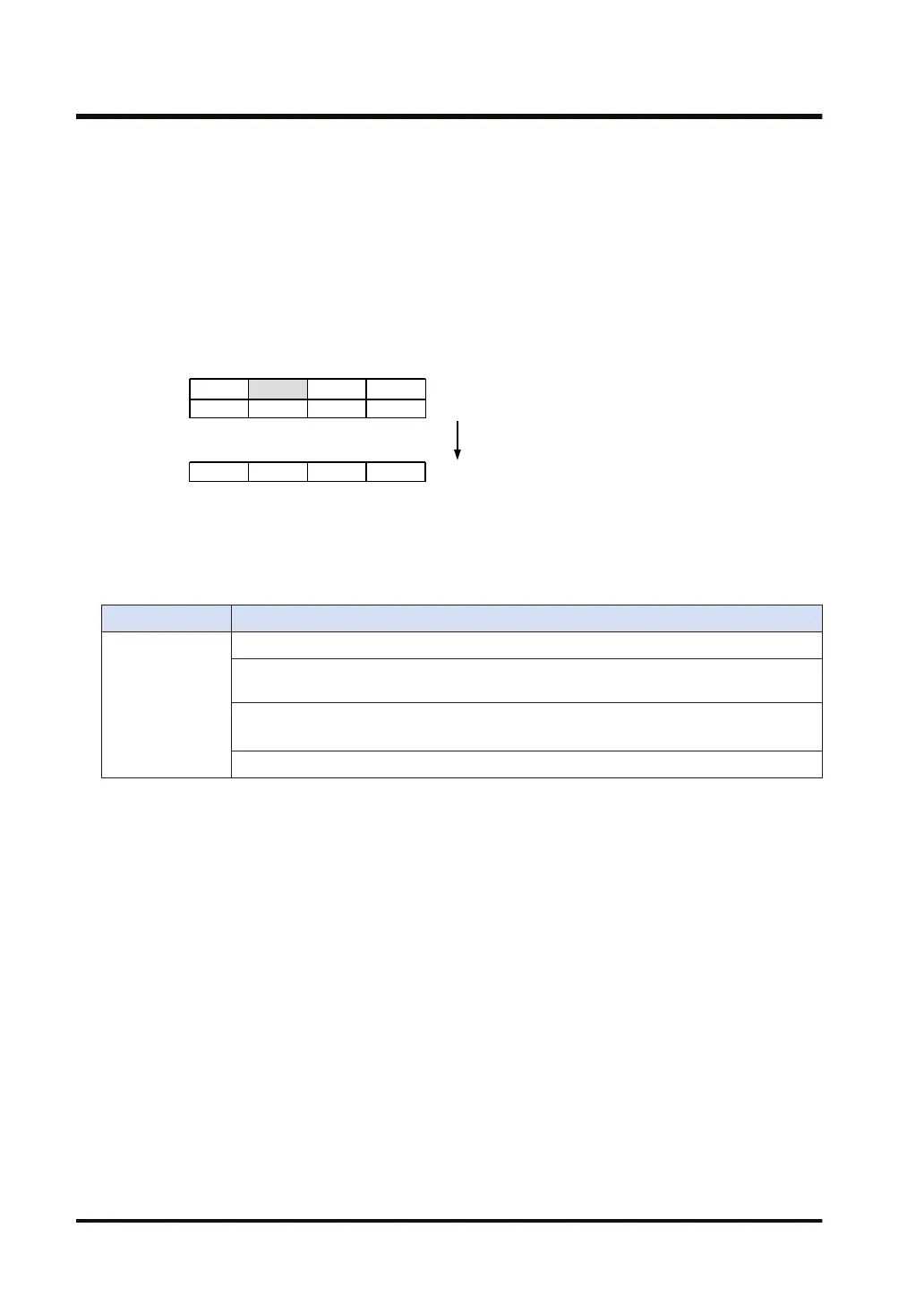
0000 0001 0000 0000
DT10
0000 0000 0000 0000
DT11
Example) [S]…DT10 [n]…H 0005 [D]…DT20
Bit 8, counted from the lowest bit of DT10, is ON.
Conversion-enabled bits are DT10 to DT11 (32 bits from DT10).
The bit numbers that are ON in these two-word area are stored in a decimal form from Bit 0 of
DT20.
DGT S , S1 , n , D , D1
Transfer [n] digits from the [S1]th digit of the area specified by [S], to the [D1] digit of the 16-bit
data specified by [D]. Transfer starts with the 0th digit, 1st digit, 2nd digit, and 3rd digit by every
four bits from the lower level.
■
Precautions for programming
● If an unsigned constant U is specified for [S], it should be converted as Hex data.
■
Flag operations
Name Description
SR7
SR8
(ER)
To be set in the case of out-of-range in indirect access (index modification).
To be set when the conversion-enabled bit length (nL) is not in the following range: 1 ≤ nL ≤
8.
To be set (for consistency) when the sum of the result output starting bit number "nH" and
the conversion-enabled bit length "nL" is not in the following range: 1 ≤ nH + nL ≤ 16.
To be set when the data to be encoded is all "0".
7.9 ENCO (Encoding)
7-22 WUME-FP7CPUPGR-12

 Loading...


