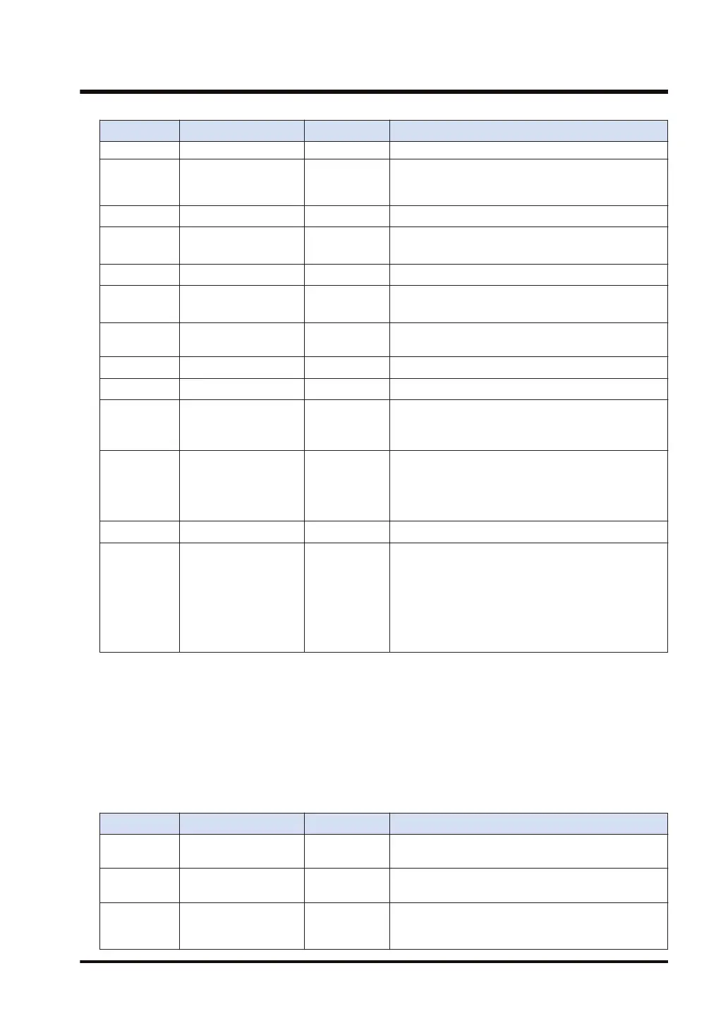
Operand Parameter Range Settings
PLC link: U1 to U16 (Default: 0)
[S+2] Baud rate setting U0 to U10
U0: 300, U1: 600, U2: 1200, U3: 2400, U4: 4800, U5:
9600, U6: 19200, U7: 38400, U8: 57600, U9: 115200,
U10: 230400 bps
[S+3] Data length setting U0, U1 U0: 7-bit length, U1: 8-bit length
[S+4] Parity setting U0 to U2
U0: No parity, U1: Odd parity, U2: Even parity, U3:
Parity fixed to 0
(Note 3)
[S+5] Stop bit length setting U0, U1 U0: 1 bit, U1: 2 bits
[S+6]
RS/CS enabled or
disabled
(Note 1)
U0, U1 U0: Disable, U1: Enable
[S+7] Send waiting time U0 to U10000
U0: Immediate Effective time = Un x 0.01 ms (0 to
100 ms)
[S+8] Start code STX U0, U1 U0: Disable, U1: Enable
[S+9] Terminator setting U0 to U3 U0: cR; U1: cR+Lf; U2: Time; U3: ETX
[S+10]
Terminator judgement
time
U0 to U10000
U0: For 32 bits
Effective time = Un × 0.01 ms (Only enabled when
the end setting is "Time".)
[S+11] Modem initialization U0 to U2
U0: Not initialize
U1: Execute the first initialization only
U2: Re-execute initialization at the time of setting.
(Note 2)
[S+12] Reserved area U0 U0
[S+13] Communication option U0, U1
bit 0: Used to select whether to continue or stop the
PLC link.
0 = The PLC link stops when a communication error
occurs.
1 = The PLC link continues even when a
communication error occurs.
bit 1 to 15: Reserved
(Note 1) RS/CS can be selected only when a 1-channel, 5-wire communication cassette (product number
AFP7CCS2) is used.
(Note 2) The modem is initialized when the power is on, PMSET/pPMSET instruction is executed, and the RUN
mode is turned ON. Initialization is executed only in the first session. (Excluding when the power
supply is turned off and then on again.)
(Note 3) U3 can be specified only for a built-in SCU. In addition, parity bit is fixed to 0 when data is sent, and
the parity bit is not checked when data is received.
PLC link W0 setting (Setting is enabled when the communication mode is set to the PLC link
mode; only COM1 is enabled)
Operand Parameter Range Settings
[S+14]
Link area block
number
U0, U1 Block number of link relay/link register area
[S+15]
PLC link W0 maximum
station number
U2 to U16 PLC link W0 maximum station number
[S+16] Range of link relays U0 to U64
Specify the range of link relays used for
communication (specification by number of words,
relative values within the specified block)
15.8 PMSET / pPMSET (Change of SCU Parameters)
WUME-FP7CPUPGR-12 15-53

 Loading...


