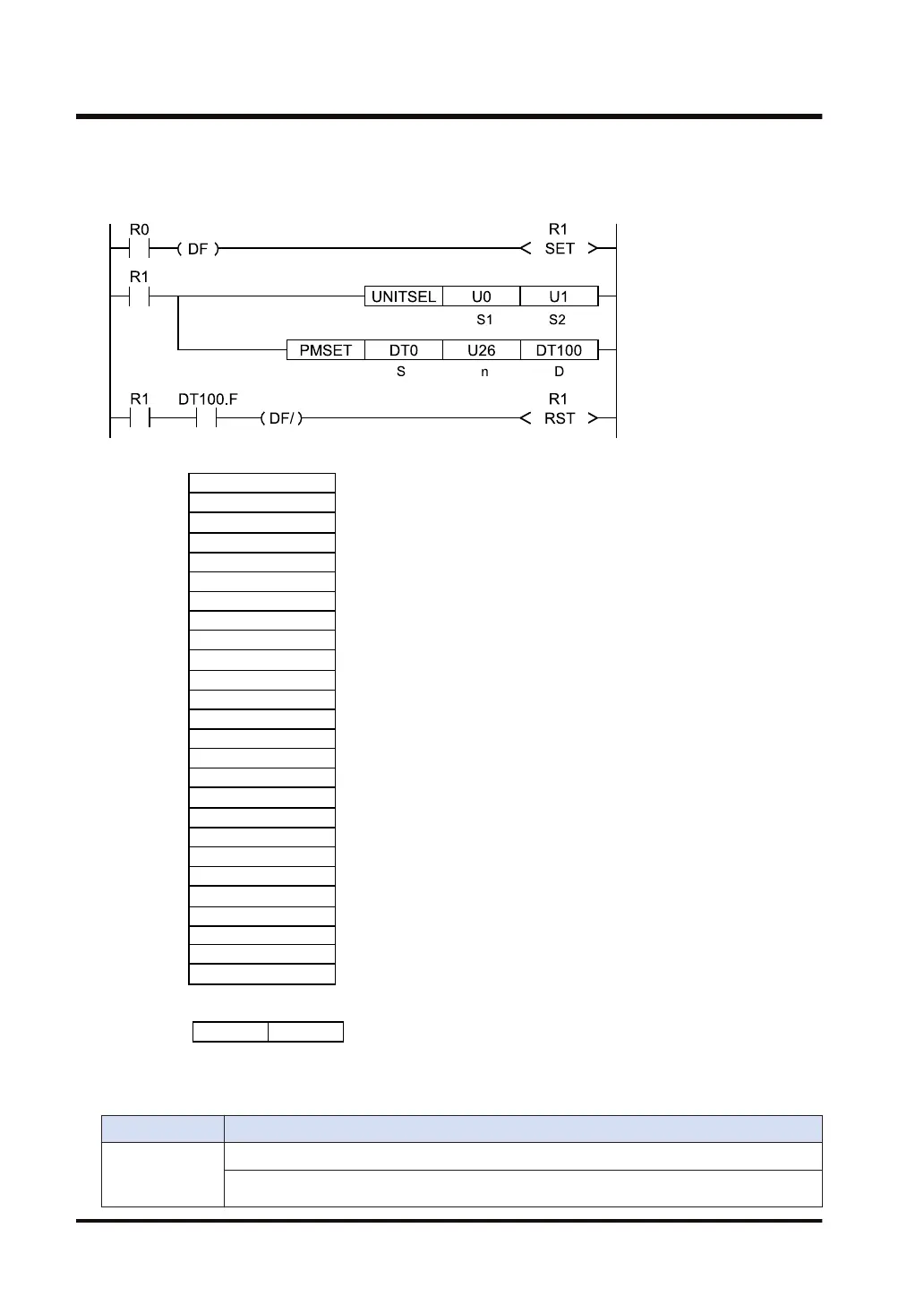
● For the PMSET instruction, it is necessary to turn ON the execution condition of the PMSET
instruction until the end of processing, and turn OFF the execution condition at a scan in
which the end of data transmission is confirmed.
H 0 H 0
High byte Low byte
DT100
Processing result ('0' for normal completion)
Communication mode
Station number setting
Baud rate setting
Data length setting
Parity setting
Stop bit length setting
RS/CS enabled or disabled
Send waiting time
Start code STX
Terminator setting
Terminator judgement time
Modem initialization
Reserved area
Communication option
Link area block number
PLC link W0 maximum station number
Range of link relays
Range of link registers
Link relay sending start number
Size of link relay send area
Link register sending start number
Size of link register send area
Reserved area
Reserved area
Reserved area
Reserved area
U 0
U 0
U 0
U 0
U 9
U 1
U 5
U 1
U 1
U 0
U 0
U 0
DT0
DT1
DT2
DT3
DT4
DT5
DT6
DT7
DT8
DT9
DT10
DT11
U 0
U 32
U 0
U 0
U 0
U 0
U 0
U 16
U 32
U 64
U 0
U 19
U 0
U 0
DT12
DT13
DT14
DT15
DT16
DT17
DT18
DT19
DT20
DT21
DT22
DT23
DT24
DT25
■
Flag operations
Name Description
SR7
SR8
(ER)
To be set in the case of out-of-range in indirect access (index modification).
To be set when the COM port specified by UNITSEL does not exist.
15.8 PMSET / pPMSET (Change of SCU Parameters)
15-56 WUME-FP7CPUPGR-12

 Loading...


