13
RFL Electronics Inc. June 10, 2002
RFL 9300DCDR
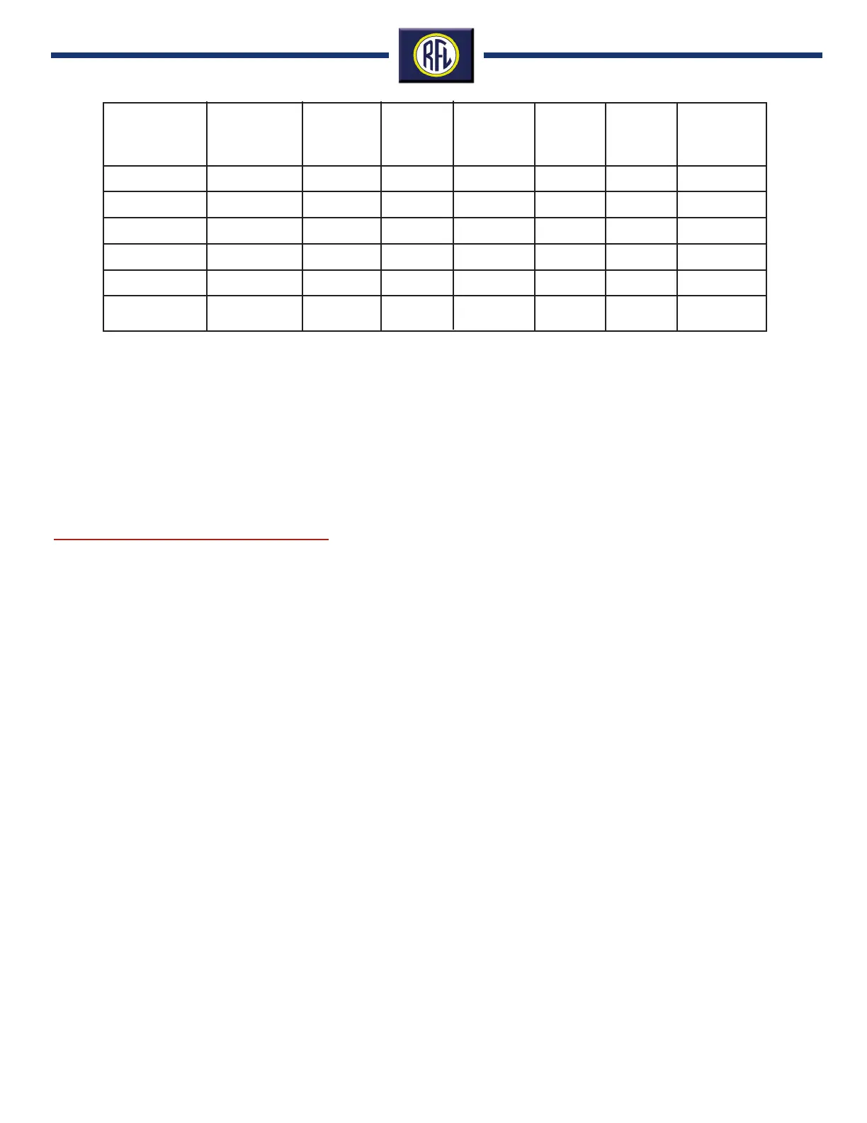
Table 1. RFL 9300 singlewidth fiber optic interface input/output characteristics
Wavelength
and
Emitter Type
Fiber Type
Mating
Connector
Type
Output
Level
Receiver
Sensitivity
System
Gain
1
Typical
Distance
(km)
2
Typical
Distance
(miles)
850 nm LED
1300 nm LED
1300 nm LED
1300 nm Laser
1550 nm Laser
850 nm LED
Short Haul
Multimode
Multimode
Singlemode
Singlemode
Singlemode
Multimode
ST
ST
ST
ST
ST
ST
-18 dBm
-13 dBm
-17 dBm
0 dBm
-3 dBm
-19 dBm
-43 dBm
-40 dBm
-40 dBm
-40 dBm
-40 dBm
-32 dBm
25 dB
27 dB
23 dB
40 dB
37 dB
13 dB
8 km
18 km
29 km
59 km
102 km
1 km
5 miles
11 miles
18 miles
36.5 miles
63 miles
.6 miles
Note:
1. System gain is based on power coupled into fiber.
2. Typical distances listed are based on the following assumptions for system loss. As actual losses will vary from
one installation to another, the distance covered by your system may vary.
Connector Losses (total of both ends): ST Connectors 2 dB
Fiber Losses:
850-nm Multimode 3dB/km 1300-nm Multimode 1dB/km
300-nm Singlemode 0.5 dB/km 1500-nm Singlemode .25dB/km
Splice Losses: One splice every 2 km, at .05 db loss per splice.
System Margin: 5 dB additional loss added to calculations to compensate for all other losses.
BASE SYSTEM:
The RFL 9300 relay is housed in a 19” rack mountable chas-
sis. The chassis is constructed utilizing plug in modules to
permit reconfiguring the relay in the field with different com-
munication interfaces or converting from two to three termi-
nal line applications.
SINGLE CHANNEL COMMUNICATIONS OPTIONS:
Select the type of communication interface required. Single
pole relays cannot be applied over VF channels.
SECOND CHANNEL COMMUNICATIONS OPTIONS:
Select the type of communication interface required for the
second channel. A second channel is required for Dual chan-
nel and all three terminal line applications. If a higher data
rate communication channel (fiber or direct digital) is selected
as the primary channel, a modem interface cannot be com-
bined to operate as the second channel. A dedicated fiber
optic channel may be used for the primary channel and a
digital channel may be used as the backup or one channel
of a three terminal line application.
AC CURRENT:
Select the appropriate value of the secondary CT current
that will be applied to the relay.
RFL 9300 Charge Comparison Relay Ordering Guide
MIXED CT RATIOS:
The RFL 9300 relay must compare the same magnitudes of
current between all terminals. If the turns ratios of the CT’s
at each terminal are not the same, the current transformers
in the RFL 9300 must be modified. Select Yes and advise
the transformer ratios existing at each terminal.
DC INPUT VOLTAGE:
This defines the power supply input voltage and the direct
transfer trip keying input voltage.
CONFIGURATION:
The RFL 9300 can be applied on either two or three terminal
lines. Three terminal line configurations require a second
communication channel option and a second communica-
tions controller module for that channel. Two terminal appli-
cations, operating with either a single or redundant commu-
nications channels, only require one communications con-
troller module. Converting an existing two terminal RFL 9300
relay for a three terminal application, requires adding a sec-
ond set of communication modules and a second communi-
cations controller module.