8.23
Date Code 20171006 Instruction Manual SEL-400 Series Relays
Monitoring
Station DC Battery System Monitor
Set the low end of the allowable dc battery system voltage according to the rec-
ommendations of C37.90–1989 (R1994) IEEE Standard for Relays and Relay
Systems Associated with Electric Power. Section 6.4 in this standard is titled
Allowable Variation from Rated Voltage for Voltage Operated Auxiliary Relays.
This section calls for an 80 percent low-end voltage and 28, 56, 140, or 280 Vdc
high-end voltages for the popular nominal station battery voltages. Table 8 .8 lists
expected battery voltages under various conditions using commonly accepted
per-cell voltages.
Use the expected battery voltages of Tabl e 8.9 to determine the relay station dc
battery monitor threshold settings. Table 8.9 shows these threshold settings for a
nominal 125-Vdc battery system (the Vdc1 input) and a nominal 48-Vdc battery
system (the Vdc2 input).
AC Ripple
Another method for determining whether the substation battery charger has failed
is to monitor the amount of ac ripple on the station dc battery system. The IEEE
C37.90-1989 standard also identifies an “Allowable AC Component in DC Con-
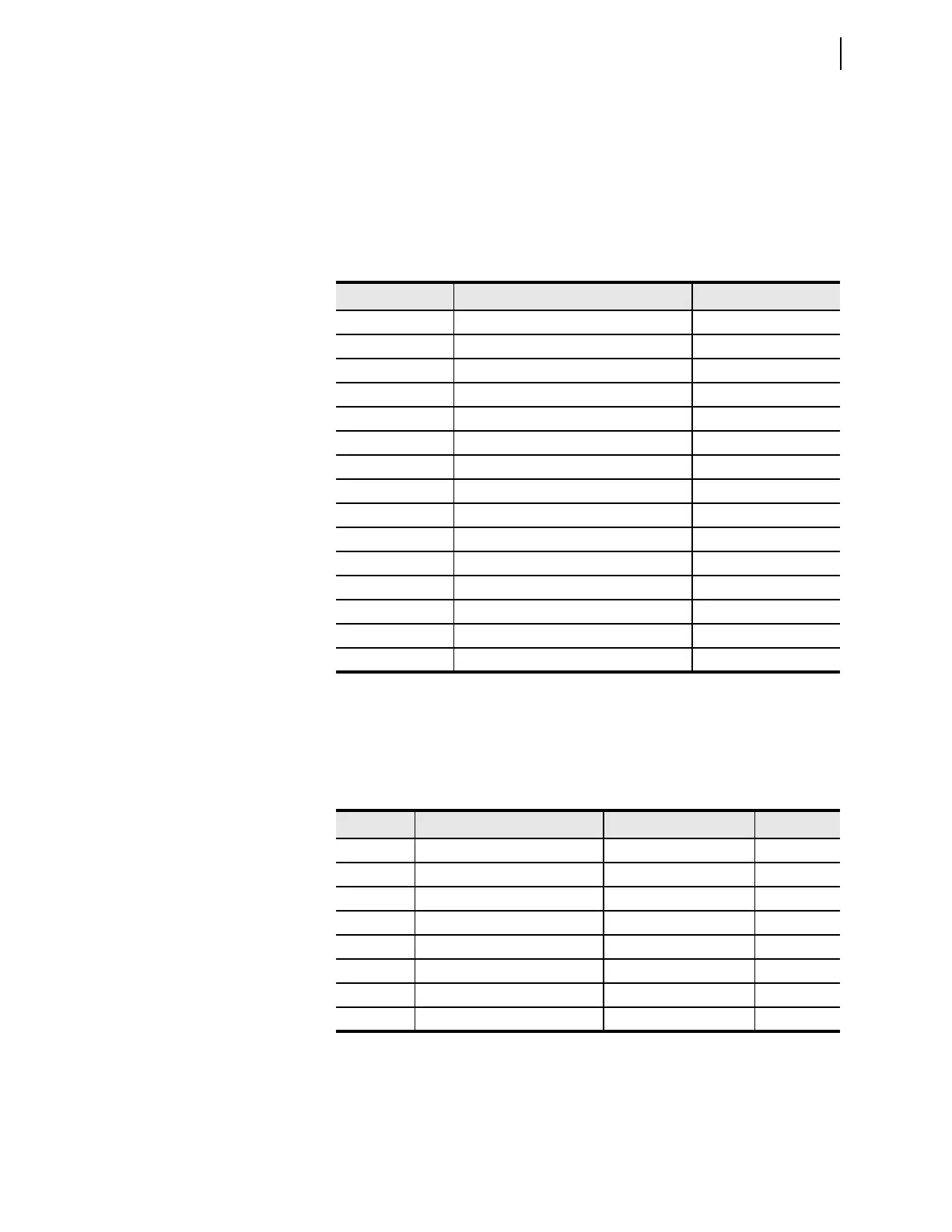
Table 8.8 Example DC Battery Voltage Conditions
Condition Calculation Battery Voltage (Vdc)
Trip/Close 80% • 125 Vdc 100.0
Open-Circuit 60 (cells) • 2.06 (volts/cell) 123.6
Float Low 60 (cells) • 2.15 (volts/cell) 129.0
Float High 60 (cells) • 2.23 (volts/cell) 133.8
Equalize Mode 60 (cells) • 2.33 (volts/cell) 139.8
Trip/Close 80% • 48 Vdc 38.4
Open-Circuit 24 (cells) • 2.06 (volts/cell) 49.4
Float Low 24 (cells) • 2.15 (volts/cell) 51.6
Float High 24 (cells) • 2.23 (volts/cell) 53.5
Equalize Mode 24 (cells) • 2.33 (volts/cell) 55.9
Trip/Close 80% • 24 Vdc 19.2
Open-Circuit 12 (cells) • 2.06 (volts/cell) 24.7
Float Low 12 (cells) • 2.15 (volts/cell) 25.8
Float High 12 (cells) • 2.23 (volts/cell) 26.8
Equalize Mode 12 (cells) • 2.33 (volts/cell) 28.0
Table 8.9 Example DC Battery Monitor Settings—125 Vdc for Vdc1 and 48 Vdc
for Vdc2
Setting Description Indication Value (Vdc)
DC1LFP Low-fail threshold, Mon. 1 Poor battery performance 100
DC1LWP Low-warning threshold, Mon. 1 Charger malfunction 127
DC1HWP High-warning threshold, Mon. 1 Equalization 137
DC1HFP High-fail threshold, Mon. 1 Charger malfunction 142
DC2LFP Low-fail threshold, Mon. 2 Poor battery performance 38
DC2LWP Low-warning threshold, Mon. 2 Charger malfunction 50
DC2HWP High-warning threshold, Mon. 2 Equalization 55
DC2HFP High-fail threshold, Mon. 2 Charger malfunction 57