10.3
Date Code 20171006 Instruction Manual SEL-400 Series Relays
Testing, Troubleshooting, and Maintenance
Testing Philosophy
TiDL Commissioning
The Time-Domain Link (TiDL) system uses a commissioning feature to identify
that the connected remote Axion nodes meet the requirements of the supported
topologies for the applied relay. These topologies are a balance between copper
reduction and number of nodes. The nodes must be connected in one of the sup-
ported topologies so that the relay will map the voltages and currents accordingly.
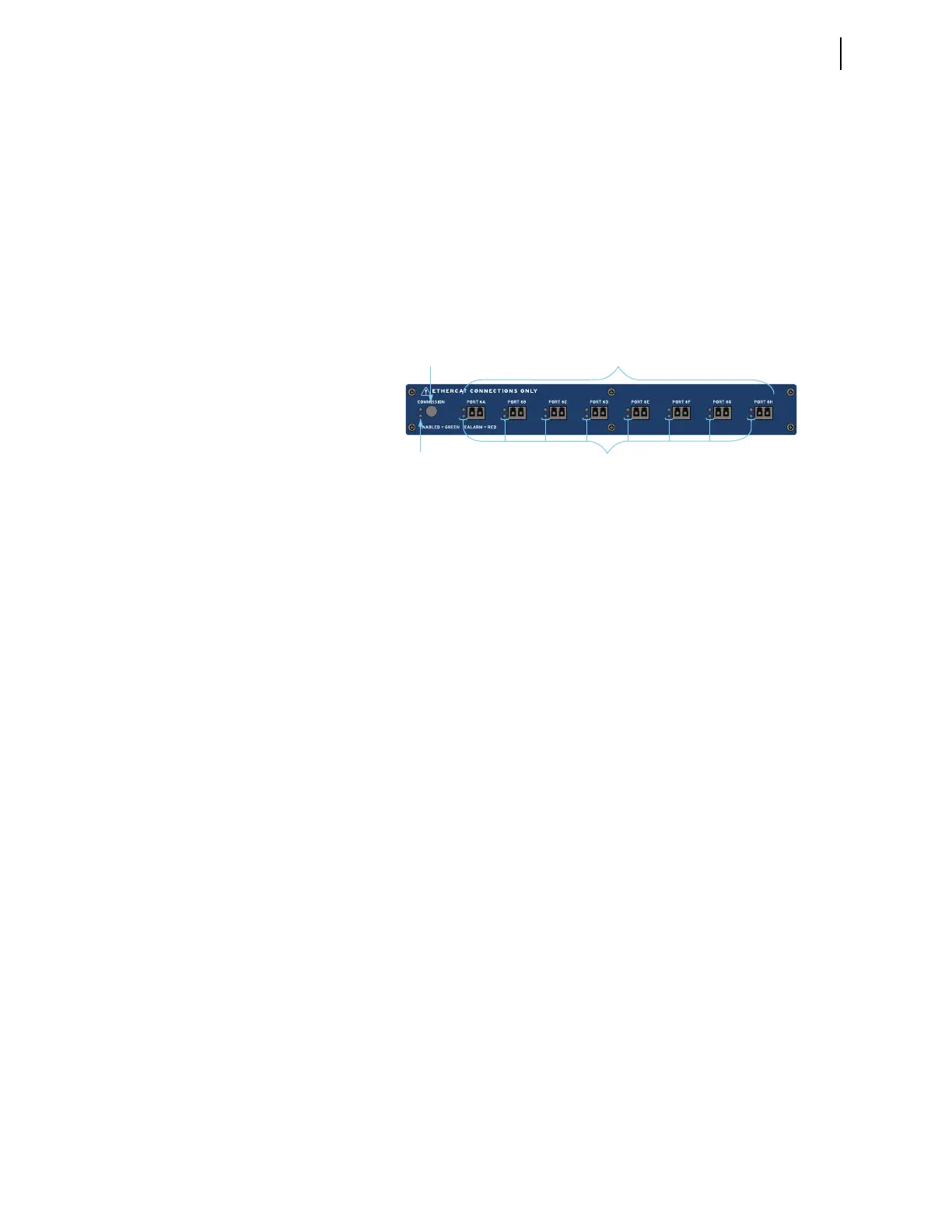
The SEL-400 series relay will have a new interface on its back panel that replaces
the original CT and PT input connections. These standard inputs are replaced
with a remote module interface that supports eight fiber-optic ports, labeled
PORT 6A–PORT 6H (see Figure 10.1).
Once all of the remote Axion nodes are connected to the relay, press the COMMIS-
SION pushbutton on the remote module interface. This process will verify that the
connected ports and Axion nodes are installed according to one of the supported
topologies. Once the process is complete, the topology will be stored in memory.
At each additional startup of the relay, the firmware will validate that the con-
nected modules match those of the stored configuration. It will recognize if any
of the CT/PT modules within the node have changed. If the topology needs to be
changed (e.g., modules are added or replaced), the system will need to be recom-
missioned by pressing the COMMISSION pushbutton.
When the commissioning and validation of the topology is complete, the voltages
and currents will be mapped according to the topology assignments (see
Section 2: Installation in the product-specific instruction manual). Secondary
injection testing will take place at each Axion node. Test sources will be required
to inject voltages and currents into the Axion node to verify the correct installa-
tion and mapping. Monitoring of the voltages and currents will remain in the con-
trol house with the relay.
In a TiDL application, the relay will have I/O on both the main board (100-level
inputs and outputs) and one additional I/O board (200-level inputs and outputs).
All other I/O will be received from the remote Axion modules and are mapped to
the 300-, 400-, and 500-level inputs and outputs in the relay.
Use the METER command on the relay to verify the ac current and voltage mag-
nitude and phase rotation (see Examining Metering Quantities on page 3.35).
Use the PUL command on the relay to pulse relay control output operation and
monitor the outputs on the relay and at the Axion node. Using a test set, voltages
and currents can be applied to the remote inputs on the Axion and then monitored
on the relay interface.
Figure 10.1 Remote Module Interface
Commissioning
Button
Commission LED
for Network Status
Eight Fiber-Optic 100 Mbps
EtherCAT Ports
LEDs for Remote
Node Status