10.25
Date Code 20171006 Instruction Manual SEL-400 Series Relays
Testing, Troubleshooting, and Maintenance
Maintenance
Step 6. Remove the front panel.
a. Unscrew the front cover of the relay.
b. Slowly pull the front cover off of the relay.
There will be a short ribbon cable between the front panel of the
relay and the main board of the relay that will prevent the relay
front panel from being pulled more than five inches from the
relay. Do not let the relay front panel hang from this ribbon cable.
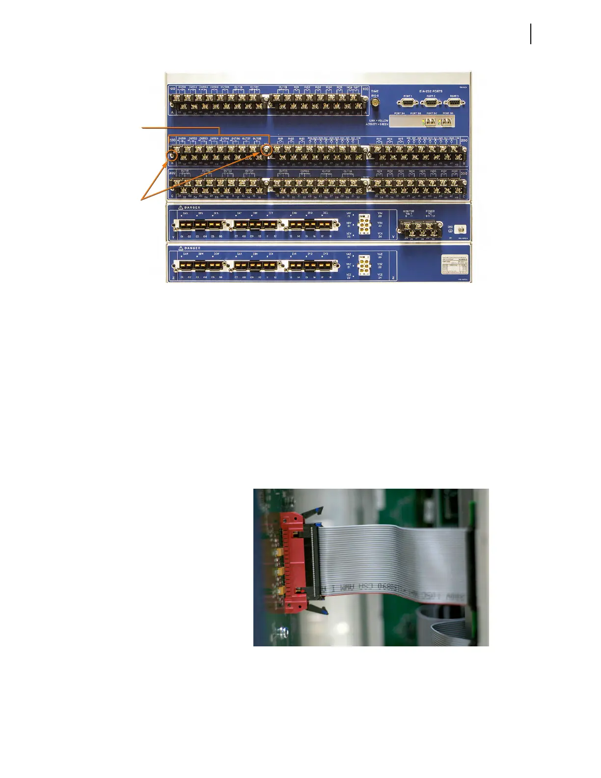
c. Remove the ribbon cable at the front panel by pushing the cable
retention levers toward the back of the front panel, as shown in
Figure 10.13.
If your front panel is equipped with auxiliary trip and close
pushbuttons, remove the connectors to the pushbuttons connected
at the front panel and the expansion I/O board.
Step 7. Remove the power supply, expansion I/O and calibration board rib-
bon cables from their connectors on the main board (see
Figure 10.14).
Figure 10.12 SEL-400 Series Relay Rear Panel
Terminal
Block
Connector
Screws
Figure 10.13 Front-Panel Ribbon Cable Connector With Clasps Open