10.26
SEL-400 Series Relays Instruction Manual Date Code 20171006
Testing, Troubleshooting, and Maintenance
Maintenance
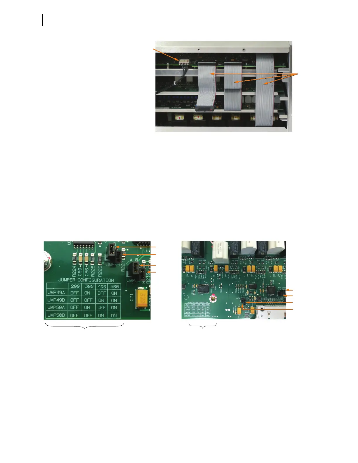
Step 8. Remove the main board power cable (white connector) from the
main board by lifting up the retaining tabs on top of the header and
sliding the connector out.
Do not bend the retaining tabs any higher than is necessary to remove
the connector as this could damage the tabs.
Step 9. Use the Jumper Configuration table shown in Figure 10.15 to con-
firm that the jumper arrangement on the I/O board matches the cor-
rect jumper configuration for the interface board being installed. For
example, the jumper configuration in Figure 10.15 (a) is for an inter-
face board being installed at the 300 level (i.e., the jumpers are set to
ON, OFF, ON, OFF).
Step 10. Install the drawout tray with the I/O interface board.
a. Position the drawout tray edges into the left-side and right-side
internally mounted slots.
b. Slide the I/O interface board into the relay by pushing the front
edge of the board drawout tray.
Figure 10.14 Main Board Cable Connections
Ribbon
Cables
Main Board
Power Cable
Figure 10.15 I/O Board Jumper Configuration
JMP49A = ON
JMP49B = OFF
JMP50A = ON
JMP50B = OFF
Jumper Configuration Table
Jumper Configuration Table
JMP2A = ON
JMP2B = OFF
JMP1B = OFF
JMP1A = ON
(a)
(b)