11.13
Date Code 20171006 Instruction Manual SEL-400 Series Relays
Time and Date Management
Time-Synchronized Events
Use Equation 11.1 to calculate the generation supplied from Substation S and
Substation R, plus the load at Substation T.
Equation 11.1
The complex power generation supplied by Substation S is:
The complex power generation supplied by Substation R is:
The load at Substation T supplied by Substation S is:
The load at Substation T supplied by Substation R is:
The total load at Substation T is:
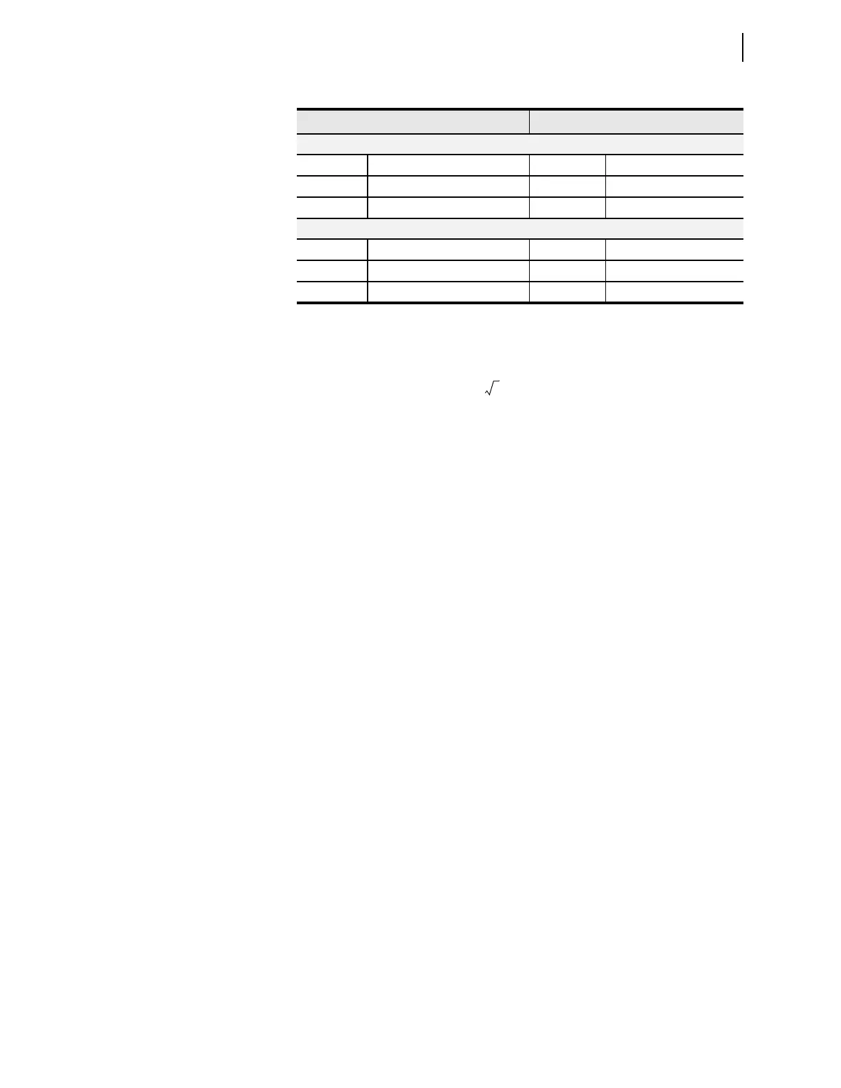
SEL-421 at Substation T Looking Toward Substation S
V
AT–S
295.603 kV –1.6° I
AT – S
238.995 A –138.1°
V
BT–S
295.603 kV 238.4° I
BT–S
238.995 A 101.9°
V
CT–S
295.603 kV 118.4° I
CT–S
238.995 A –18.1°
SEL-421 at Substation T Looking Toward Substation R
V
AT–R
295.603 kV –1.6° I
AT – R
234.036 A 135.8°
V
BT–R
295.603 kV 238.4° I
BT–R
234.036 A 15.8°
V
CT–R
295.603 kV 118.4° I
CT–R
234.036 A –104.2°
where:
S
3
=
Three-phase complex power (MVA)
P
3
=
Three-phase real power (MW)
Q
3
=
Three-phase imaginary power (MVAR)
V
pp
=
Phase-to-phase voltage
V
p
=
Phase-to-neutral voltage
I*
L
=
Complex conjugate of the line current
Table 11.6 SEL-421 Voltage and Current Measurement (Sheet 2 of 2)
Voltage Current
S
3ø
P
3ø
jQ
3ø
+=
3V
pp
I
L
• • =
3V
p
I
L
• • =
S
S
3 288.675 kV 0• 238.995 A 41.9–• =
154.1 MW j138.2 MVAR–=
S
R
3 303.109 kV 0.2– • 234.036 A 44.2• =
152.6 MW j148.3 MVAR+=
S
TS–
3 295.603 kV 1.6– • 238.995 A 138.1• =
153.7– MW j145.9 MVAR+=
S
TR–
3 295.603 kV 1.6– • 234.036 A 135.8– • =
152.8– MW j140.5 MVAR–=
S
T
S
TS–
S
TR–
+=
306.5– MW j5.4 MVAR+=