11.12
SEL-400 Series Relays Instruction Manual Date Code 20171006
Time and Date Management
Time-Synchronized Events
In particular, you can use fault data extracted from two relays. Use third-party
software to filter the binary COMTRADE data so that the signals are composed
of fundamental quantities only (50 Hz or 60 Hz). You can also use third-party
software to convert the binary COMTRADE data to ASCII COMTRADE files.
Use the Phasor Diagram in the SEL-5601
SYNCHROWAVE Event to select the
appropriate prefault and post-fault quantities.
Power Flow Analysis
Use SEL-400 series relays to develop instantaneous power flow data. Obtain the
voltage and current phasors from different power system buses at the same
instant and use these measurements to determine power flow at that instant. Use
the synchronized phasor measurement capabilities of the relay and the METER
PM command or a Synchrophasor Protocol to collect synchronized voltage and
current data. Use this information to confirm your power flow models.
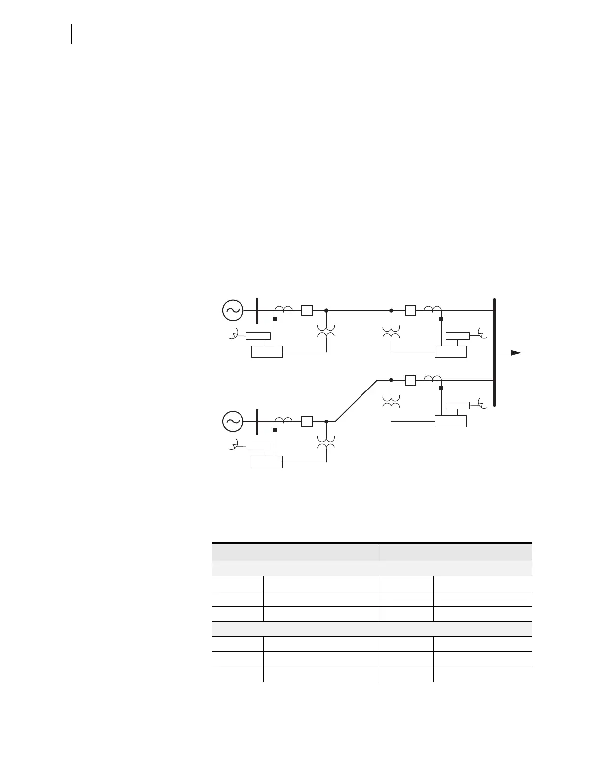
For example, consider four SEL-421 Relays installed in the power system as shown in
Figure 11.7. Substations S and R provide generation for the load at Substation T.
Table 11.8 lists the voltage and current measured by the four SEL-421 Relays at
one particular time.
Figure 11.7 500 kV Three-Bus Power System
Table 11.6 SEL-421 Voltage and Current Measurement (Sheet 1 of 2)
Voltage Current
SEL-421 at Substation S
V
AS
288.675 kV 0° I
AS
238.995 A 41.9°
V
BS
288.675 kV 240° I
BS
238.995 A –78.1°
V
CS
288.675 kV 120° I
CS
238.995 A 161.9°
SEL-421 at Substation R
V
AR
303.109 kV –0.2° I
AR
234.036 A –44.2°
V
BR
303.109 kV 239.8° I
BR
234.036 A 195.8°
V
CR
303.109 kV 119.8° I
CR
234.036 A 75.8°
S
R
T
SEL-421
GPS Rx
SEL-421
GPS Rx
SEL-421
GPS Rx
SEL-421
GPS Rx