11.11
Date Code 20171006 Instruction Manual SEL-400 Series Relays
Time and Date Management
Time-Synchronized Events
Step 6. Select settings.
a. Click the + mark next to Relay Configuration.
b. Click the Trip Logic and ER Trigger branch.
You will see the Trip Logic and ER Trigger Settings dialog box.
Step 7. Click in the ER Event Report Trigger Equation (SEL
OGIC) text
box and add OR R_TRIG PSV02 to the end of elements already in
this SEL
OGIC control equation.
Step 8. Click File > Save to save the new settings in QuickSet.
NOTE: You should be careful to
remove this event report trigger once
you have completed your testing.
Otherwise, the relay will continue to
trigger new events every day at the
programmed time.
Step 9. Upload the new settings to the relay:
a. Click File > Send.
QuickSet prompts you for the settings class or instance you want
to send to the relay.
b. Click the check box for Group 1 (or the settings group that you
are programming).
c. Click OK.
If you see no error message, the new settings are loaded in the relay.
COMTRADE File Information
Retrieve the COMTRADE files for the time-triggered data captures from each
relay with the FILE READ command.
Parse the binary COMTRADE data for the power system currents and voltages
you need to calculate system quantities.
Fault Analysis
Use the relay measurement and communications capabilities to obtain precise
simultaneous measurements from the power system at different locations. Com-
bining system measurements from a number of key substations gives you a snap-
shot picture of the phasor relationships in the power system at a particular time.
You can perform extensive fault analysis by evaluating the simultaneous mea-
surements gathered at a central computer or data server.
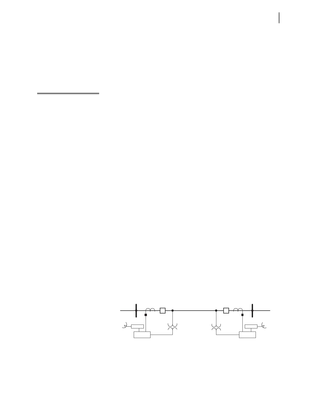
Install at least two relays in the power system to implement dynamic phasor
determination. Figure 11.6 shows an example of a 230 kV overhead transmission
line with a relay at each terminal. Connect GPS clocks (such as the SEL-2407) at
each substation to provide high-accuracy time-signal inputs for each relay.
With synchronized and time-stamped binary COMTRADE data, you can develop
automated computer algorithms for comparing these data from different locations
in the power system.
Figure 11.6 230 kV Transmission Line System
Relay
Relay
Z
1L
, Z
0L
Z
1S
, Z
0S
BK1
GPS Rx
S (Harvard) R (Princeton)
BK2
Z
1R
, Z
0R
GPS Rx