12.22
SEL-400 Series Relays Instruction Manual Date Code 20171006
Settings
Output Settings
Output Settings
The Main Board output settings consists of SELOGIC control equations
OUT101–OUT108. The defaults are relay specific; see the relay-specific instruc-
tion manual to see the defaults. Some SEL-400 series relays do not have any
main board outputs, in which case this category is not available.
NOTE: In TiDL relays, Interface
Boards 2–4 are always considered to
be available. Depending on the Axion
modules connected, these outputs
may or may not be physically present.
The Interface Board output settings consists of SELOGIC control equations
OUTx01–OUTx16 where x = 2–5, corresponding to Interface Boards 1 to 4. The
category for any interface board is only available if the interface board is
installed. The defaults are relay specific; see the relay-specific instruction manual
to see the defaults.
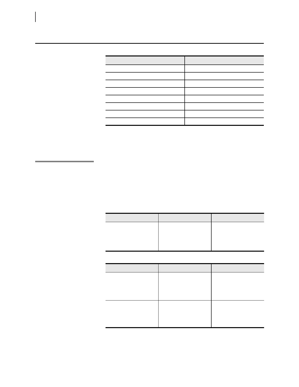
Make Table 12.35 settings if an Ethernet card is present and IEC 61850 is ordered.
Table 12.34 Output Settings Categories
Settings Reference
Main Board
Interface Board #1
Interface Board #2
Interface Board #3
Interface Board #4
Remote Analog Outputs Table 12.35
M
IRRORED BITS Transmit Equations Table 12.36
87L Communications Bits
a
a
Only available in products that support 87L communication.
Table 12.37
Ta b l e 1 2 . 35 Remote A n a lo g O u t p u t s
Label Prompt Default Value
RAO01
•
•
•
RAO64
•
•
•
NA
•
•
•
NA
Ta b l e 1 2. 36 M
IRRORED BITS Transmit Equations
Label Prompt Default Value
TMB1A
•
•
•
TMB8A
•
•
•
NA
•
•
•
NA
TMB1B
•
•
•
TMB8B
NA
•
•
•
NA