13.16
SEL-400 Series Relays Instruction Manual Date Code 20171006
SELOGIC Control Equation Programming
SEL
OGIC Control Equation Elements
NOTE: Times for protection timers
must not exceed 2,000,000 cycles for
proper operation.
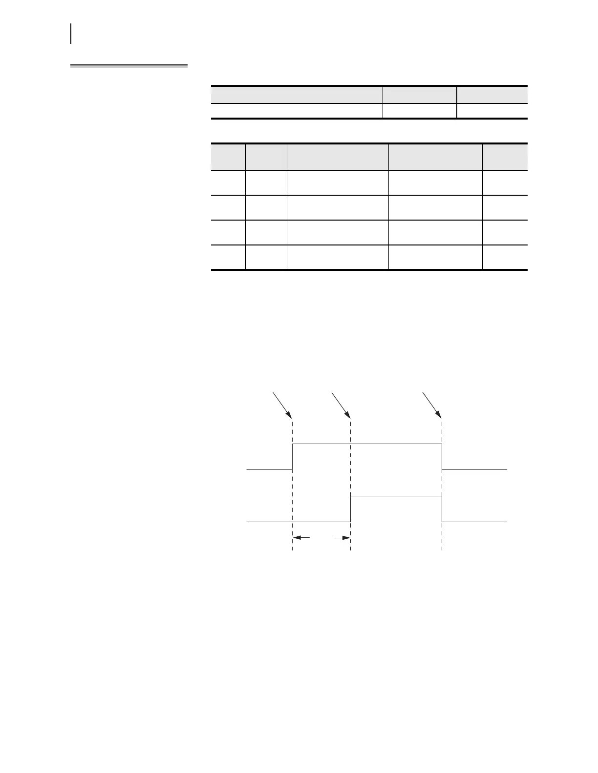
A conditioning timer output turns on and becomes logical 1, after the input turns
on and the Pickup Time expires. An example timing diagram for a conditioning
timer, PCT01, with a Pickup Time setting greater than zero and a Dropout Time
setting of zero is shown in Figure 13.3. In the example timing diagram, the Input,
PCT01IN, turns on and the timer Output, PCT01Q, turns on after the Pickup
Time, PCT01PU, expires. Because the Dropout Time setting is zero, the Output
turns off when the Input turns off.
If the Pickup Time is not satisfied, the timer Output never turns on, as illustrated
in Figure 13.4. If the input reasserts again, one or more processing intervals later,
the conditioning timer pickup timer begins timing again from zero.
Table 13.9 Conditioning Timer Quantities
Type Typical Quantity Name Range
Protection freeform conditioning timers 32 PCT01–PCT32
Table 13.10 Conditioning Timer Parameters
Type Item Description Setting
Name
Examples
Input Input Value that the relay times Boolean SELOGIC control
equation setting
PCT01IN
Input Pickup
Time
Time that the input must be
on before the output turns on
Time value in cycles PCT01PU
Input Dropout
Time
Time that the output stays on
after the input turns off
Time value in cycles PCT01DO
Output Output Timer output Value for Boolean
SEL
OGIC control equations
PCT01Q
Figure 13.3 Conditioning Timer With Pickup and No Dropout Timing Diagram
PCT01IN
PCT01Q
Input Changes
from 0 to 1
Input Changes
from 1 to 0
Pickup
Time
PCT01PU
Pickup Time
Expires