13.17
Date Code 20171006 Instruction Manual SEL-400 Series Relays
SELOGIC Control Equation Programming
SEL
OGIC Control Equation Elements
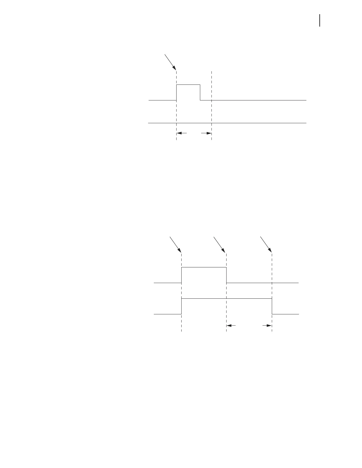
A conditioning timer output turns off when the input turns off and the Dropout
Time expires. An example timing diagram for a conditioning timer, PCT02, with
a Pickup Time setting of zero and a Dropout Time setting greater than zero is
shown in Figure 13.5. Because the Pickup Time, PCT02PU, setting is zero, the
Output, PCT02Q, turns on when the Input, PCT02IN, turns on. The Output turns
off after the Input turns off and the Dropout Time, PCT02DO, expires. If the
input reasserts before the dropout time expires, the dropout timer resets so it
begins timing again from zero when the input drops out again.
Combining the features shown above, Figure 13.6 illustrates conditioning timer
operation for use of both the pickup and dropout characteristics. The Output,
PCT03Q, turns on after the Input, PCT03IN, turns on and the Pickup Time,
PCT03PU, expires. The Output turns off after the Input turns off and the Dropout
Time, PCT03DO, expires.
Figure 13.4 Conditioning Timer With Pickup Not Satisfied Timing Diagram
Figure 13.5 Conditioning Timer With Dropout and No Pickup Timing Diagram
PCT01IN
PCT01Q
Input Changes
from 0 to 1
Pickup
Time
PCT01PU
PCT02IN
PCT02Q
Input Changes
from 0 to 1
Input Changes
from 1 to 0
Dropout Time
Expires
Dropout Time
PCT02DO