13.18
SEL-400 Series Relays Instruction Manual Date Code 20171006
SELOGIC Control Equation Programming
SEL
OGIC Control Equation Elements
Set the conditioning timer settings for Pickup and Dropout in cycles and fractions
of a cycle (represented in decimal form). The relay processes conditioning timers
once for each protection processing interval. The relay asserts the timer output on
the first processing interval when the elapsed time exceeds the setting. In most
SEL-400 series relays, the protection processing interval is 1/8 cycle (or 0.125 cycles).
See the product-specific instruction manual to determine the specific processing inter-
val. Actual settings, programming, and operation are illustrated in Example 13.7.
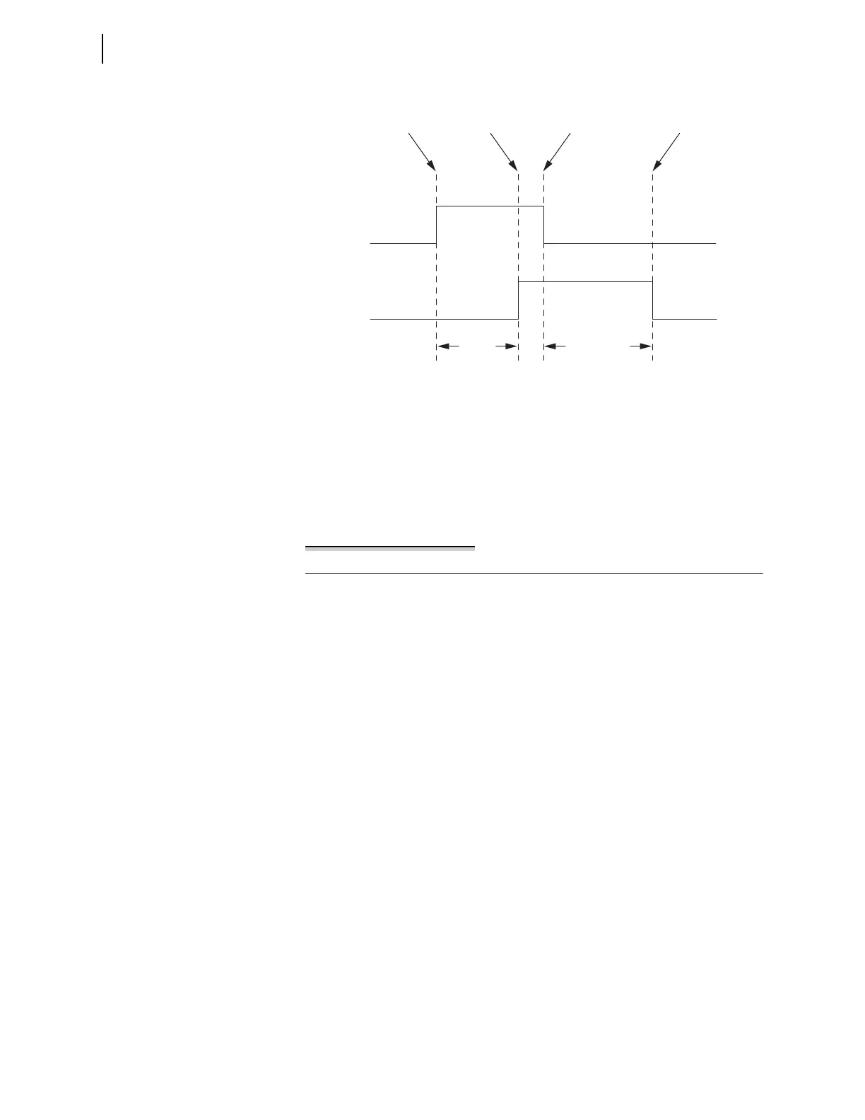
Figure 13.6 Conditioning Timer With Pickup and Dropout Timing Diagram
Example 13.7 Conditioning Timer Programming and Operation
This example uses protection freeform conditioning timer seven, PCT07.
The freeform settings are as shown here:
PCT07PU := 5.3 # Pickup set to 5.3 cycles
PCT07D0 := 6.0 # Dropout set to 6.0 cycles
PCT07IN := IN101 # Operate on the first input on the main board
PSV29 := PCT07Q # Protection SEL
OGIC control equation variable fol-
lows the timer output
The operation of the timer when IN101 turns on for 7 cycles is shown in the
timing diagram in Figure 13.7. Because the pickup setting is an uneven num-
ber of protection processing intervals (1/8 cycle), the pickup occurs on the
first 1/8th cycle after the Pickup Time of 5.3 cycles expires.
PCT03IN
PCT03Q
Input Changes
from 0 to 1
Input Changes
from 1 to 0
Dropout Time
Expires
Pickup Time
Expires
Dropout Time
PCT03DO
Pickup
Time
PCT03PU