B.5
Date Code 20171006 Instruction Manual SEL-400 Series Relays
Firmware Upgrade Instructions
Upgrade Procedure
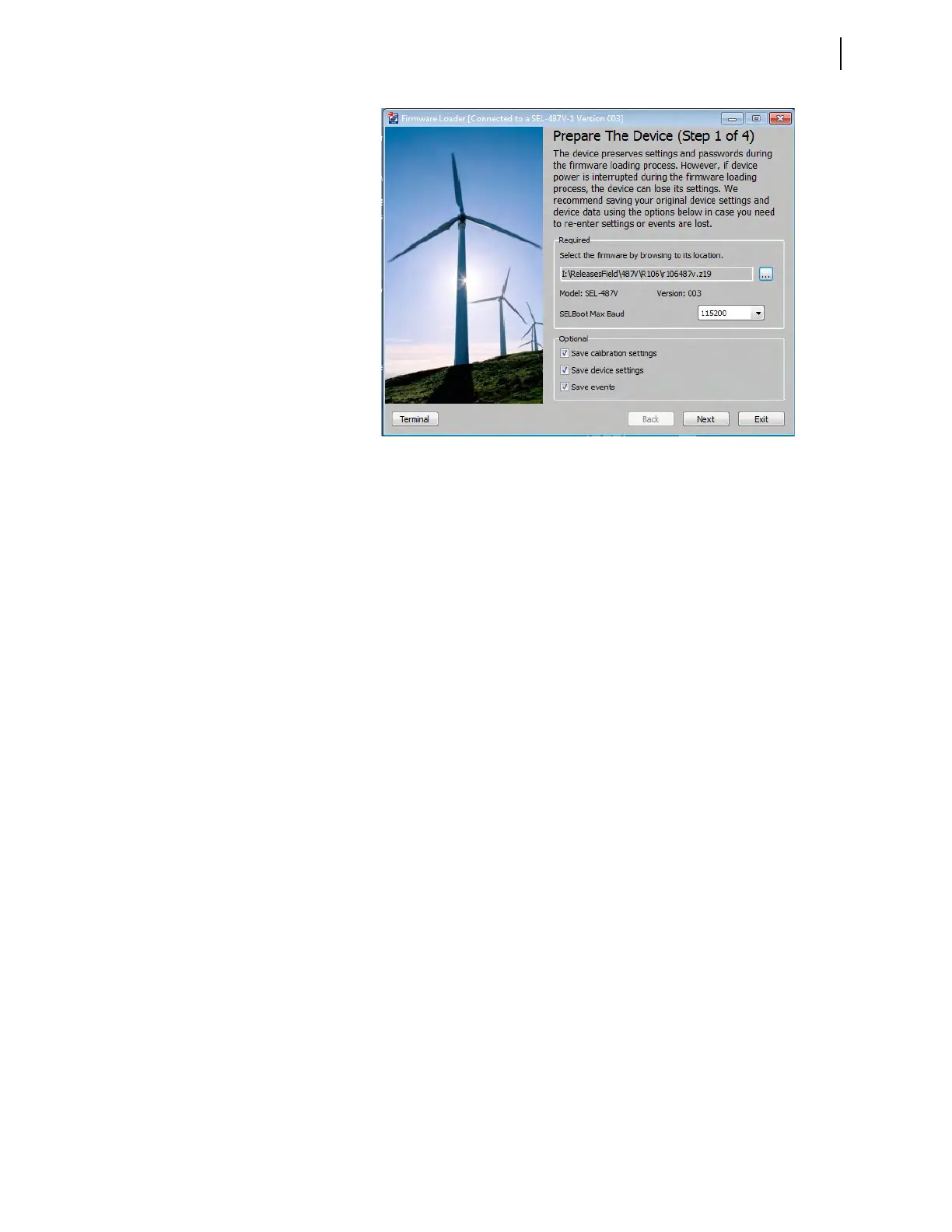
Step 4. Select the Save calibration settings check box in the Step 1 of 4
window of the Firmware Loader. These factory settings are required
for proper operation of the relay and must be reentered in the
unlikely event they are erased during the firmware upgrade process.
The Firmware Loader saves the settings in a text file on the PC.
Step 5. Select the Save device settings check box if you do not have a copy
of the relay settings. It is possible for relay settings to be lost during
the upgrade process.
Step 6. Select the Save events check box if there are any event reports that
have not been previously saved. The event history is cleared during
the upgrade process.
Step 7. Click Next.
The Firmware Loader reads the calibration settings and saves them in
a text file on the PC. Make note of the file name and the location.
If Save device settings was selected, the Firmware Loader reads all
of the settings from the relay. The software may ask if you want to
merge the settings read from the relay with existing design templates
on the PC. Click No, do not merge settings with Design Template.
The Firmware Loader will suggest a name for the settings, but the
suggested name can be modified as desired.
If Save events was selected, the Event History window will open to
allow the events to be saved. See Section 2: PC Software for more
information.
Step 8. If you use the Breaker Wear Monitor, click the Terminal button in
the lower left portion of the Firmware Loader to open the terminal
window. From the Access Level 1 prompt, issue the BRE command
and record the internal and external trip counters, internal and exter-
nal trip currents for each phase, and breaker wear percentages for
each phase.
Step 9. Enable Terminal Logging capture (see Section 2: PC Software) and
issue the following commands to save stored data. It is possible for
these data to be lost during the firmware upgrade process.
a. MET E—accumulated energy metering
b. MET D—demand and peak demand
Figure B.1 Prepare the Device (Step 1 of 4)