3.43
Date Code 20171006 Instruction Manual SEL-400 Series Relays
Basic Relay Operations
Examining Relay Elements
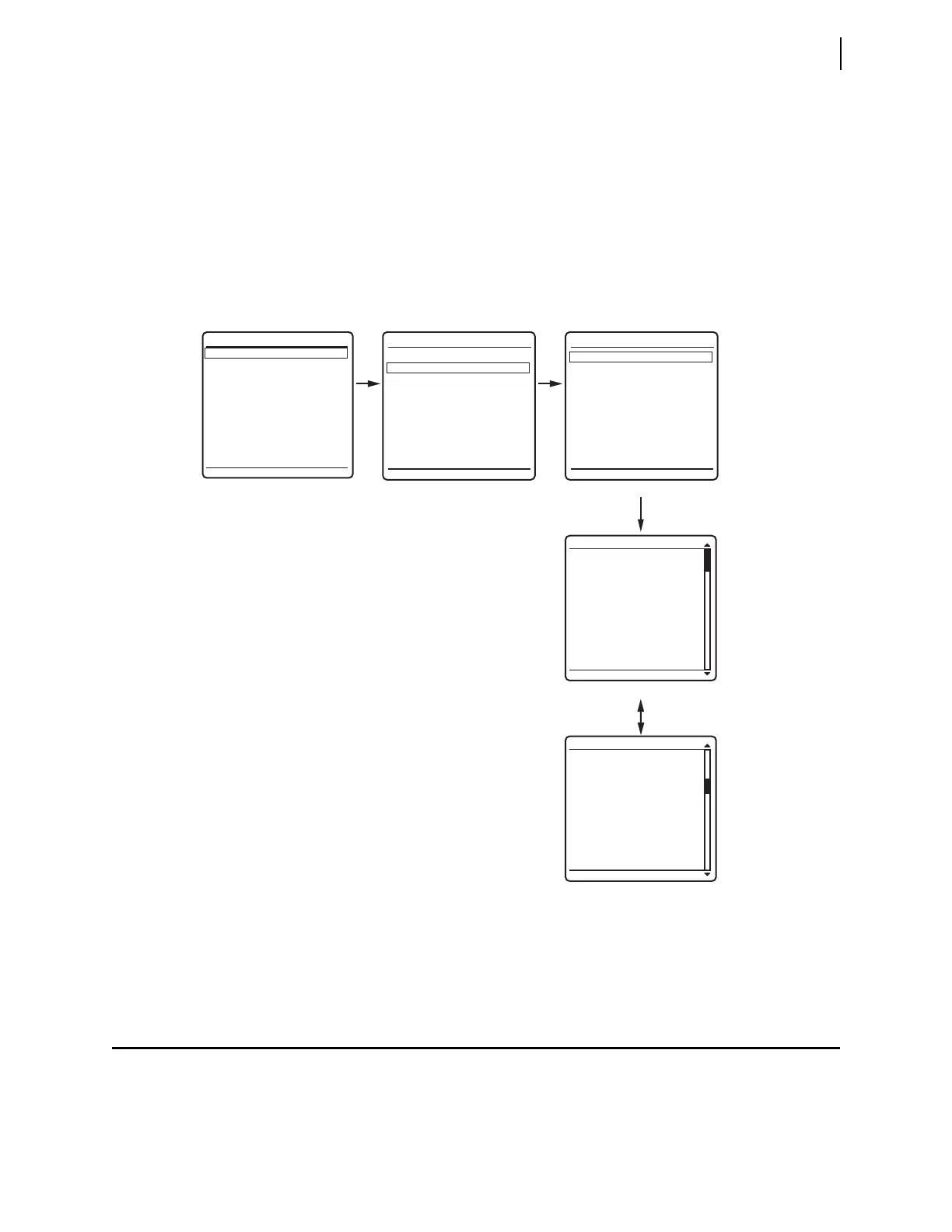
Step 4. View the metering screens.
a. Press the Up Arrow and Down Arrow navigation pushbuttons to
highlight the
FUNDAMENTAL METER action item, as shown in
Figure 3.34(b).
b. Press the ENT pushbutton.
The relay displays the first
FUNDAMENTAL METER screen, shown in
Figure 3.34(c).
c. Use the Up Arrow and Down Arrow navigation pushbuttons to move
among the fundamental line quantities metering screens.
Step 5. Press the ESC pushbutton repeatedly to return to the
MAIN MENU.
Examining Relay Elements
Use the communications port TAR command or the front panel to display the
state of relay elements, control inputs, and control outputs. Viewing a change in
relay element (Relay Word bit) status is a good way to verify the pickup settings
you have entered for protection elements.
Figure 3.34 Front-Panel Screens for METER
VOLTAGE (kV)
VA = 133.9 0°
VB = 133.9 -120°
VC = 133.9 120°
CURRENT (A)
IA = 400.5 -31°
IB = 397.4 -151°
IC = 400.1 90°
FREQ = 60.00 Hz
VDC1 = 9.2 V
VDC2 = 10.7 V
FUND LINE METER
VOLTAGE (kV)
VAB = 231.8 30°
VBC = 231.8 -90°
VCA = 232.2 150°
FUND LINE METER
METER
EVENTS
BREAKER MONITOR
RELAY ELEMENTS
LOCAL CONTROL
SET/SHOW
RELAY STATUS
VIEW CONFIGURATION
DISPLAY TEST
RESET ACCESS LEVEL
MAIN MENU
METER MENU
RMS METER
FUNDAMENTAL METER
ENERGY METER
MAX/MIN
METER SUBMENU
LINE
BREAKER 1
•
•
•
(a) (b) (c)
(d)
(e)