3.48
SEL-400 Series Relays Instruction Manual Date Code 20171006
Basic Relay Operations
Reading Oscillograms, Event Reports, and SER
Step 5. Connect a test source to the relay.
a. Set the current output of a test source to zero output level.
b. Connect a single-phase current output of the test source to the
IAW analog input.
Step 6. View the target status change.
a. Increase the current source to produce a current magnitude
greater than 15.00 A secondary in the relay.
b. Observe the LED next to Pushbutton 6 on the SEL-451 front panel.
You will see the LED illuminate when the input current exceeds
the 50P1P setting threshold.
Reading Oscillograms, Event Reports, and SER
SEL-400 series relays have great capabilities for storing and reporting power sys-
tem events. These include high-resolution oscillography with sampling as high as
8 kHz, event reports that encompass important variables in the power system, and
the SER that reports changing power system conditions and relay operating
states.
You can view oscillograms taken from high-resolution raw data or from filtered
event report data. Each type of presentation gives you a unique view of the power
system. High-resolution oscillograms are useful for viewing system transients
and dc artifacts outside the relay filter system; event report oscillograms give you
a picture of the quantities that the relay used in the protection algorithms.
The examples listed in this subsection give step-by-step procedures to acquaint
you with these features. Section 9: Reporting provides a complete discussion of
these relay features.
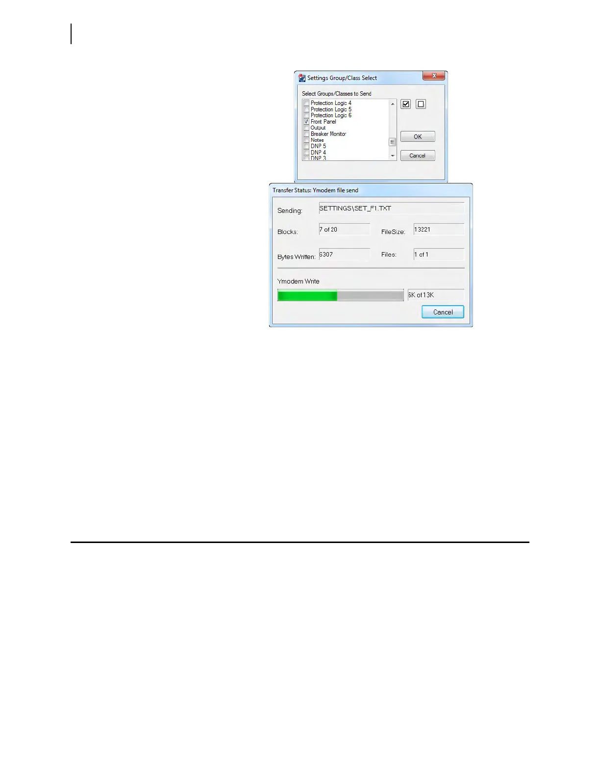
Figure 3.38 Uploading Front-Panel Settings to the Relay