3.67
Date Code 20171006 Instruction Manual SEL-400 Series Relays
Basic Relay Operations
Operating the Relay Inputs and Outputs
Setting Outputs for Tripping and Closing
To actuate power system circuit breakers, you must configure the control outputs
to operate the trip bus and close bus. The relay uses internal logic and SEL
OGIC
control equations to activate the control outputs.
Trip Output Signals
All SEL-400 series relays are capable of three-pole tripping and some are capable
of single-pole tripping. There are many Relay Word bits (e.g., T3P1, T3P2, and
3PT) that you can program to drive control outputs to trip circuit breakers. See
Section 5: Protection in the product-specific instruction manual for complete
information on tripping equations and settings. For target illumination at tripping,
see Section 4: Front-Panel Operations.
Close Output Signals
Some SEL-400 series relays feature an automatic recloser for single-circuit
breaker and two-circuit breaker applications, with as many as four autoreclose
shots. See Section 6: Autoreclosing for more information.
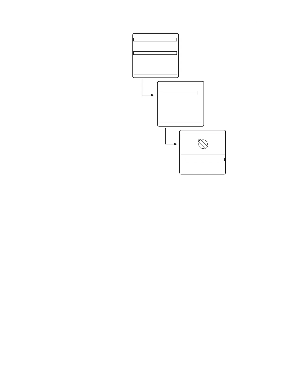
Figure 3.60 Front-Panel LOCAL CONTROL Screens
1 ON
0 OFF
5 MVA XFMR Fans
1
0
METER
EVENTS
BREAKER MONITOR
RELAY ELEMENTS
LOCAL CONTROL
SET/SHOW
RELAY STATUS
VIEW CONFIGURATION
DISPLAY TEST
RESET ACCESS LEVEL
MAIN MENU
LOCAL CONTROL
--BREAKER CONTROL--
5 MVA XFMR Fans
--OUTPUT TESTING--
(a)
(b)
(c)