4.25
Date Code 20171006 Instruction Manual SEL-400 Series Relays
Front-Panel Operations
Front-Panel Menus and Screens
Output Testing
NOTE: The circuit breaker control
enable jumper BREAKER must be
installed to perform output testing.
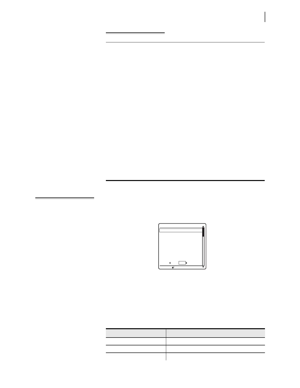
You can check for proper operation of the relay control outputs by using the OUT-
PUT TESTING
submenu of the LOCAL CONTROL menu. A menu screen similar to
Figure 4.28 displays a list of the control outputs available in your relay configuration.
Set/Show
You can use the SET/SHOW menus to examine or modify relay port settings,
Global settings, active group settings, and date/time. See Table 4 .9 for a list of
settings classes and settings that you can change from the front panel.
To change the local bit state, select the bit and set it to the state you want. In
addition, you can delete the local bit, which changes the state of this local bit
to logical 0 when you save the settings. To delete, use the front-panel set-
tings. When using a communications port and terminal, use the text-edit
mode line setting editing commands at the Local Bits and Aliases prompt to
go to the line that lists Local Bit 9. (See Text-Edit Mode Line Editing on
page 3.22 for information on text-edit mode line editing.) To delete Local
Bit 9, type DELETE <Enter> after the line that displays Local Bit 9 infor-
mation. For example, if a previously programmed Local Bit 9 appears in the
SET F line numbered listings on Line 1, then typing DELETE <Enter> at
Line 1 deletes Local Bit 9.
Next, set the local bit. In the Front Panel settings (SET F), enter the following:
1: LB09,“Bus Tie Interlock”,“Closed (OK to TIE)”,“Open (No TIE)”,N
This sets Local Bit 9 to “Bus Tie Interlock” with the set state as “Closed (OK
to TIE)” and the clear state as “Open (No TIE).”
Assign the local bit to a relay output. In the Output settings (SET O), set the
SEL
OGIC control equation, OUT201, to respond to Local Bit 9.
OUT201 := LB09
Use the appropriate interface hardware to connect the circuit breaker inter-
lock to OUT201.
Example 4.4 Enabling Local Bit Control (Continued)
Figure 4.28 OUTPUT TESTING Screen
OUTPUT TESTING
OUT201
OUT202
OUT203
OUT204
OUT205
OUT206
OUT207
OUT208
NO YES
PULSE OUTPUT?
PRESS TO PULSE
Table 4.9 Settings Available From the Front Panel (Sheet 1 of 2)
Class/Setting Description
PORT Relay communications port settings
GLOBAL Global relay settings
GROUP Relay group settings