4.33
Date Code 20171006 Instruction Manual SEL-400 Series Relays
Front-Panel Operations
Operation and Target LEDs
Operation and Target LEDs
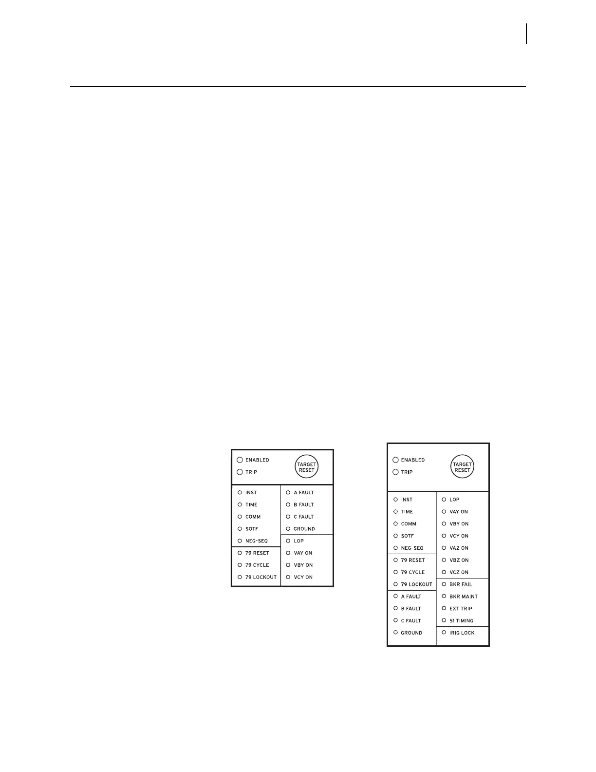
The relay gives you at-a-glance confirmation of relay conditions via operation
and target LEDs. These LEDs are located in the middle of the relay front panel.
SEL-400 series relays provide either 16 or 24 LEDs depending on ordering
option.
You can reprogram all of these indicators except the ENABLED and TRIP LEDs to
reflect other operating conditions than the factory-default programming
described in this subsection. Settings Tn_LED are SEL
OGIC control equations
that, when asserted during a relay trip event, light the corresponding LED (n = 1–24).
LED positions are described in parentheses next to each LED in Figure 4.40.
Set TnLEDL := Y to latch the LEDs during trip events; when you set
TnLEDL := N, the trip latch supervision has no effect and the LED follows the
state of the Tn_LED SEL
OGIC control equation. The relay reports these targets in
event reports; set the alias name listed in the report (as many as seven characters)
by aliasing the Tn_LED bits with the SET T command or with QuickSet. In 12-
pushbutton models, the asserted and deasserted colors for the LED are deter-
mined with settings TnLEDC. Options include red, green, amber, or off. In some
SEL-400 series relays, if TnLEDL = Y, the relay latches the target on the rising
edge of the target bit. In these relays, to cause the bits to latch with trip, modify
the equation to include AND R_TRIG TRIP. Refer to the Target LEDs subsection
in the relay-specific Front-Panel Operations section to determine if the LED
latches with the rising edge of TRIP or on the rising edge of Tn_LED.
After setting the target LEDs, issue the TAR R command to reset the target
LEDs. For a description of the default LED behavior for a specific relay, see the
Front Panel Operations section in the relay-specific instruction manual.
Use the slide-in labels to mark the LEDs with custom names. Configurable label
templates included on relay-specific Product Literature CDs allow you to cus-
tomize the front-panel labels.
Figure 4.40 SEL-451 Factory-Default Front-Panel Target Areas (16 or 24 LEDs)
(1)
(2)
(3)
(4)
(5)
(6)
(7)
(8)
(9)
(10)
(11)
(12)
(13)
(14)
(15)
(16)
(1)
(2)
(3)
(4)
(5)
(6)
(7)
(8)
(9)
(10)
(11)
(12)
(13)
(14)
(15)
(16)
(17)
(18)
(19)
(20)
(21)
(22)
(23)
(24)