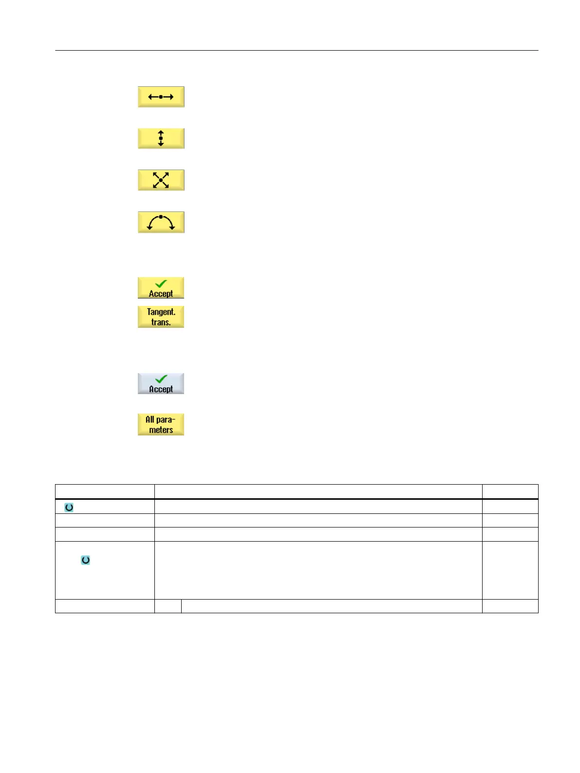
The "Straight line (e.g. Z)" input window opens.
- OR
The "Straight line (e.g. X)" input window opens.
- OR
The "Straight line (e.g. ZX)" input window opens.
- OR
The "Circle" input window opens.
4. Enter all the data available from the workpiece drawing in the input
screen (e.g. length of straight line, target position, transition to next ele‐
ment, angle of lead, etc.).
5. Press the "Accept" softkey.
The contour element is added to the contour.
6. When entering data for a contour element, you can program the transi‐
tion to the preceding element as a tangent.
Press the "Tangent to prec. elem." softkey. The "tangential" selection
appears in the parameter α2 entry field.
7. Repeat the procedure until the contour is complete.
8. Press the "Accept" softkey.
The programmed contour is transferred into the process plan (program
view).
9. If you want to display further parameters for certain contour elements,
e.g. to enter additional commands, press the "All parameters" softkey.
Contour element "Straight line e.g. Z"
Parameters Description Unit
Z End point Z (abs or inc) mm
α1 Starting angle to Z axis Degrees
α2 Angle to the preceding element Degrees
Transition to next ele‐
ment
Type of transition
● Radius
● Undercut
● Chamfer
Radius R Transition to following element - radius mm
Programming technology functions (cycles)
10.3 Contour turning
Turning
Operating Manual, 06/2019, A5E44903486B AB 449