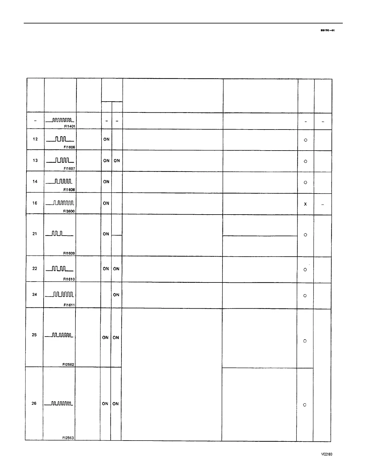
DIAGNOSTIC TROUBLE CODES
HINT:
• If a malfunction is detected during the diagnostic trouble code check, refer to the circuit indicated
in the table, and turn to the corresponding page.
• Your readings may vary from the parameters listed in the table, depending on the instruments used.
(1) Heated oxygen sensor output is less than
0.45 V for at least 90 sacs. when heated
oxygen sensor is warmed up (racing at
2.000 rpm) and drive at 50 – 100 km/h
*4
(2) When the engine speed varies by more
than15 rpm over the preceding crankshaft
position period during a period of 50 seconds
during idling with the engine coolant temp.
75C (167’F) or more.
*6
(2 trip detection logic) (1) and (2)
• Engine ground bolt loose
• Open in E1 circuit
• Short in injector circuit
• Fuel line pressure (Injector
. leakage, etc.)
• Open or short in cold start
injector circuit
• Cold start injector
• Open or short in heated oxygen
sensor circuit
• Heated oxygen sensor
• Engine coolant temp. sensor
• Volume air flow meter
• Compression pressure
• ECM
• Engine ground bolt loose
• Open in E1 circuit
• Open in injector circuit
• Fuel line pressure (Injector
blockage, etc. )
• Open or short in heated
oxygen sensor circuit
• Heated oxygen sensor
• Ignition system
• Engine coolant temp. sensor
• Volume air flow meter (Air intake)
• ECM
(1) Open or short in heater circuit of heated
oxygen sensor for 0.5 sec. or more. (HT)
(2) At normal driving speed (below 60 mph and
engine speed is above 1,500 rpm), amplitude
of heated oxygen sensor signal (OX) is
reduced to between 0.35 – 0.70 V
continuously for 60 secs. or more.
*6
(2 trip detection logic) (2)
Open or short in engine coolant temp. sensor
circuit for 0.5 sec. or more. (THW)
• Open or short in intake air temp.
circuit
. Intake air temp. sensor
• ECM
• Open or short in heated oxygen
sensor circuit
• Heated oxygen sensor
• ECM
• Open or short in heater circuit
of heated oxygen sensor
• Heated oxygen sensor heater
• ECM
• Open or short in NE, G circuit
• Distributor
• Open or short in STA circuit
• ECM
IGF signal from igniter is not input to ECM for 6
consecutive ignition.
• Open or short in IGF or IGT
circuit from igniter to ECM
• Igniter
• ECM
• . Open or short in engine
coolant temp. sensor circuit
• Engine coolant temp. sensor
• ECM
NE signal is not input to ECM for 0.1 sec. or
more when engine speed is 1,000 rpm or
more.
No G or NE signal –is input to the ECM for 2
secs.
or more after STA turns 4N.
Open or short in intake air temp. sensor circuit
for 0.5 sec. or more. (THA)
• Open or short in NE circuit
• Distributor
• ECM
Normal signal is not output from ECM CPU.
Output when no other code is recorded.
Number of
blinks
Malfunction
Indicator
Lamp
Heated
Oxygen
Sensor
Signal
*1
Mal–
function
Indicator
Lamp
Air–Fuel
Ratio
Lean
Mal–
function
Engine
Coolant
Temp.
Sensor
Signal
Air– Fuel
Ratio
Rich Mal–
function
Intake
Air
Temp.
Sensor
Signal
Diagnosis
A/T
Control
Signal
Trouble Area
Ignition
Signal
*
2
Memory
RPM
Signal
EG2–197
EG2–199
RPM
Signal
System
Code
No.
See
Page
• ECM
*3
ON
EG2–199
Normal
EG2–190
EG2–192
Normal
Mode
EG2–195
EG2–193
IG–1 6
*7
ON
N.A.
N.A.
N.A.
N.A.
Test
Mode
–ENGINE MFI SYSTEM
EG2–176