3. INSTALL PULLEY
(a) Install the pulley to the rotor shaft by tightening the
pulley nut by hand.
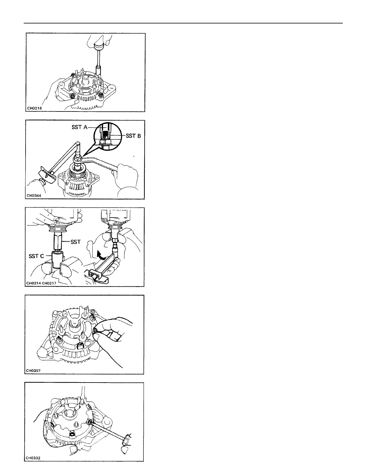
(b) Hold SST A with a torque wrench, and tighten SST
B clockwise to the specified torque.
SST 09820–63010
Torque: 39 N–m (400 kgf –cm, 29 ft–Ibf)
(c) Check that SST A is secured to the pulley shaft.
ASSEMBLY OF GENERATOR
(See page CH–5)
1. INSTALL ROTOR TO DRIVE END FRAME
2. INSTALL REAR END FRAME
(a) Using a plastic–faced hammer, lightly tap in the rear
end frame.
(b) Install the four nuts.
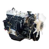
(d) As shown in the illustration, mount SST C in a vise,
and install the generator with SST (A and B) to SST C.
(e) To torque the pulley nut, turn SST A in the direction
shown in the illustration.
Torque: 110 N–m (1,125 kgf –cm, 81 ft–lbf )
(f) Remove the generator with SST (A and B) from SST C.
(g) Turn SST B and remove SSTs A and B.
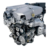
4. INSTALL RECTIFIER HOLDER
(a) Install the four rubber insulators on the lead wires.
(b) Install the rectifier with the four screws.
–CHARGING SYSTEM Generator
CH–14