3. INSTALL ENGINE WIRE
(a) Install the engine wire with the two bolts.
(b) Connect the following connectors:
• Injector connectors
• RH ground strap
• Engine coolant temp. sender gauge connector
• Engine coolant temp. sensor connector
• Cold start injector time switch connector
• Knock sensor connector
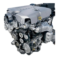
(h) Place the two delivery pipes together with the six
injectors in position on the intake manifold.
(i) Temporarily install the four spacers and nuts.
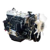
(j) Check that the injectors rotate smoothly.
HINT: If injectors do not rotate smoothly, the probable
cause is incorrect installation of 0– rings. Replace the
O–rings.
(k) Position the injector connector upward.
2. INSTALL NO.2 AND NO.3 FUEL PIPES
(a) Install the No.2 fuel pipe with four new gaskets and
two union bolts.
Torque: 34 N–m (350 kgf–cm, 25 ft–Ibf)
(b) Install the No.3 fuel pipe with four new gaskets and
two union bolts.
Torque: 34 N–m (350 kgf–cm, 25 ft–lbf)
(I) Tighten the four nuts holding the delivery pipes to the
intake manifold.
Torque: 13 N–m (130 kgf–cm, 9 ft–lbf)
(m) Install the No. 1 fuel pipe to the No.3 bearing cap with
the bolt.
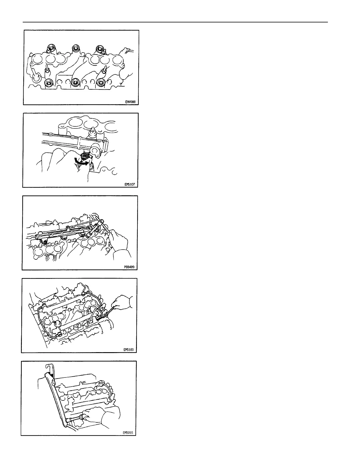
(e) Install a O–ring to the spacer.
(f) Place the six spacers and insulators into the injector
holes.
(g) Place the four spacers on the stud bolts.
–ENGINE MFI SYSTEM
EG2–227