MP-2B4CT
Maximum module transit
delay
8.0 μs transponder configuration OTU4 client with GFEC
to 100G QPSK network with 25% SD-FEC (5 TPC
iterations)
6.0 μs transponder configuration OTU4 client with GFEC
to 100G QPSK network with 25% SD-FEC (1 TPC
iterations)
8.0 μs transponder configuration 100GBASE-R client
with FEC to 100G QPSK network with 25% SD-FEC (5
TPC iterations)
7.0 μs transponder configuration 100GBASE-R client
with FEC to 100G QPSK network with 25% SD-FEC (1
TPC iterations)
6.0 μs muxponder configuration OTU4 client with GFEC
to 200G 16QAM network with 25% SD-FEC (5 TPC
iterations)
5.0 μs muxponder configuration OTU4 client with GFEC
to 200G 16QAM network with 25% SD-FEC (1 TPC
iterations)
6.7 μs muxponder configuration OTU4 client with GFEC
to 300G (2x150G lane 8QAM) network with 25% SD-
FEC (5 TPC iterations)
5.5 μs muxponder configuration OTU4 client with GFEC
to 300G (2x150G lane 8QAM) network with 25% SD-
FEC (1 TPC iterations)
6.7 μs muxponder configuration 100GBASE-R client with
FEC to 300G (2x150G lane 8QAM) network with 25%
SD-FEC (5 TPC iterations)
5.5 μs muxponder configuration 100GBASE-R client with
FEC to 300G (2x150G lane 8QAM) network with 25%
SD-FEC (1 TPC iterations)
Table 68: System Performance
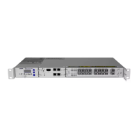
Pluggable Transceivers
Interface specification depends on the QSFP transceiver in the configuration. For details
about the individual transceiver types, see Pluggable Transceivers. For a list of
compatible pluggable transceivers for the MP-2B4CT, see Pluggable Transceiver
Compatibility.
l Pluggable Transceivers
l Handling Pluggable Transceivers
l Electrostatic Discharge Damage Prevention and Warning
FSP 3000R7 High-Density Subshelf Guide - R17.2 - Issue:B 128