132 AMCC Proprietary
Revision 1.01 - February 19, 2007
PPC405 Processor
Preliminary User’s Manual
1. Write a 0 to TCR[PIE]. This prevents PIT activity from causing interrupts.
2. Write a 0 to TCR[ARE]. This disables the PIT auto-reload feature.
3. Write zeroes to the PIT to halt PIT decrementing. Although this action does not cause a pit PIT interrupt to
become pending, a near-simultaneous decrement to 0 might have done so.
4. Write a 1 to TSR[PIS] (PIT Interrupt Status bit). This clears TSR[PIS] to 0 (see “Timer Status Register (TSR)”
on page 11-8). This also clears any pending PIT interrupt. Because the PIT stops decrementing, no further PIT
events are possible.
If the auto-reload feature is disabled (TCR[ARE] = 0) when the PIT decrements to 0, the PIT remains 0 until soft-
ware uses mtspr to reload it.
After a reset, TCR[ARE] = 0, which disables the auto-reload feature. Figure 7-4 illustrates the PIT.
7.2.1 Fixed Interval Timer (FIT)
The FIT provides timer interrupts having a repeatable period. The FIT is functionally similar to an auto-reload PIT,
except that only a smaller fixed selection of interrupt periods are available.
The FIT exception occurs on 0→1 transitions of selected bits from the time base, as shown in Table 7-2.
The TSR[FIS] field logs a FIT exception as a pending interrupt. A FIT interrupt occurs if TCR[FIE] and MSR[EE] are
enabled at the time of the FIT exception. “Fixed Interval Timer (FIT) Interrupt” on page 10-44 describes register
settings during a FIT interrupt.
The interrupt handler should reset TSR[FIS]. This is done by using mtspr to write a word to the TSR having a 1 in
TSR[FIS] and any other bits to be cleared, and a 0 in all other bits. The data written to the TSR is not direct data,
but a mask. A 1 clears a bit and a 0 has no effect.
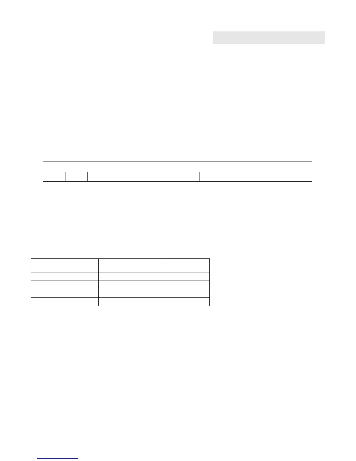
Figure 7-4. Programmable Interval Timer (PIT)
0:31 Programmed interval remaining Number of clocks remaining until the PIT event
Table 7-2. FIT Controls
TCR[FP] TBL Bit
Period
(Time Base Clocks)
Period
(200 Mhz Clock)
0, 0 23 2
9
clocks 2.56 μsec
0, 1 19 2
13
clocks 40.96 μsec
1, 0 15 2
17
clocks 0.655 msec
1, 1 11 2
21
clocks 10.49 msec