AMCC Proprietary 49
Revision 1.02 - September 10, 2007
PPC405 Processor
Preliminary User’s Manual
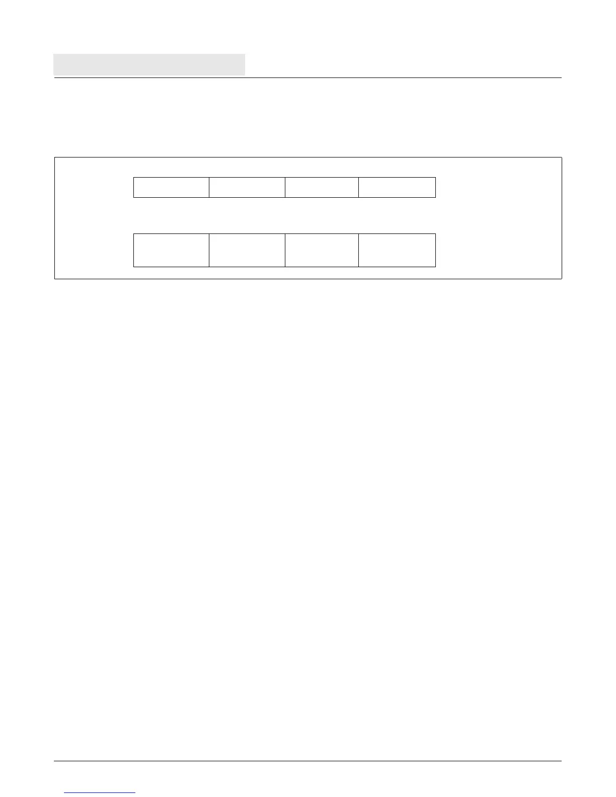
Note that the results are identical to the results of a normal load/store in a little endian storage region, as illustrated
in Figure 2-14.
The E storage attribute augments the byte-reverse load/store instructions in two important ways:
• The load/store with byte-reverse instructions do not solve the problem of fetching instructions from a storage
region in little endian format.
Only the endian storage attribute mechanism supports the fetching of little endian program images.
• Typical compilers cannot make general use of the byte-reverse load/store instructions, so these instructions
are ordinarily used only in device drivers written in hand-coded assembler.
Compilers can, however, take full advantage of the endian storage attribute mechanism, enabling application
programmers working in a high-level language, such as C, to compile programs and data structures into little
endian format.
2.6 Instruction Processing
The instruction pipeline, illustrated in Figure 2-15, contains three queue locations: prefetch buffer 1 (PFB1),
prefetch buffer 0 (PFB0), and decode (DCD). This queue implements a pipeline with the following functional
stages: fetch, decode, execute, write-back and load write-back. Instructions are fetched from the instruction cache
unit (ICU), placed in the instruction queue, and eventually dispatched to the execution unit (EXU).
Instructions are fetched from the ICU at the request of the EXU. Cacheable instructions are forwarded directly to
the instruction queue and stored in the ICU cache array. Non cacheable instructions are also forwarded directly to
the instruction queue, but are not stored in the ICU cache array. Fetched instructions drop to the empty queue
location closest to the EXU. When there is room in the queue, instructions can be returned from the ICU two at a
time. If the queue is empty and the ICU is returning two instructions, one instruction drops into DCD while the other
drops into PFB0. PFB1 buffers instructions when the pipeline stalls.
Branch instructions are examined in DCD and PFB0 while all other instructions are decoded in DCD. All
instructions must pass through DCD before entering the EXU. The EXU contains the execute, write-back and load
write-back stages of the pipe. The results of most instructions are calculated during the execute stage and written
to the GPR file during the write back stage. Load instructions write the GPR file during the load write-back stage.
Figure 2-14. Normal Word Load or Store (Little Endian Storage Region)
GPR
LSB
MSB
Memory
0x00 0x01 0x02 0x03
11 12 13 14
14 13 12 11