70 AMCC Proprietary
Revision 1.02 - September 10, 2007
PPC405 Processor
Preliminary User’s Manual
As shown in Table 3-1, tag ways A and B store instruction address bits A0:21 for each line in cache ways A and B.
Instruction address bits A19:26 serve as the index to the cache array. The two cache lines that correspond to the
same line index (one in each way) are called a congruence class.
When a cache line is to be loaded, the cache way to receive the line is determined by using an least recently-used
(LRU) policy. The index, determined by the instruction address, selects a congruence class. Within a congruence
class, the line which was accessed most recently is retained, and the other line is marked as LRU, using an LRU
bit in the tag array. The line to receive the incoming data is the LRU line. After the cache line fill, the LRU bit is then
set to identify as least-recently-used the line opposite the line just filled.
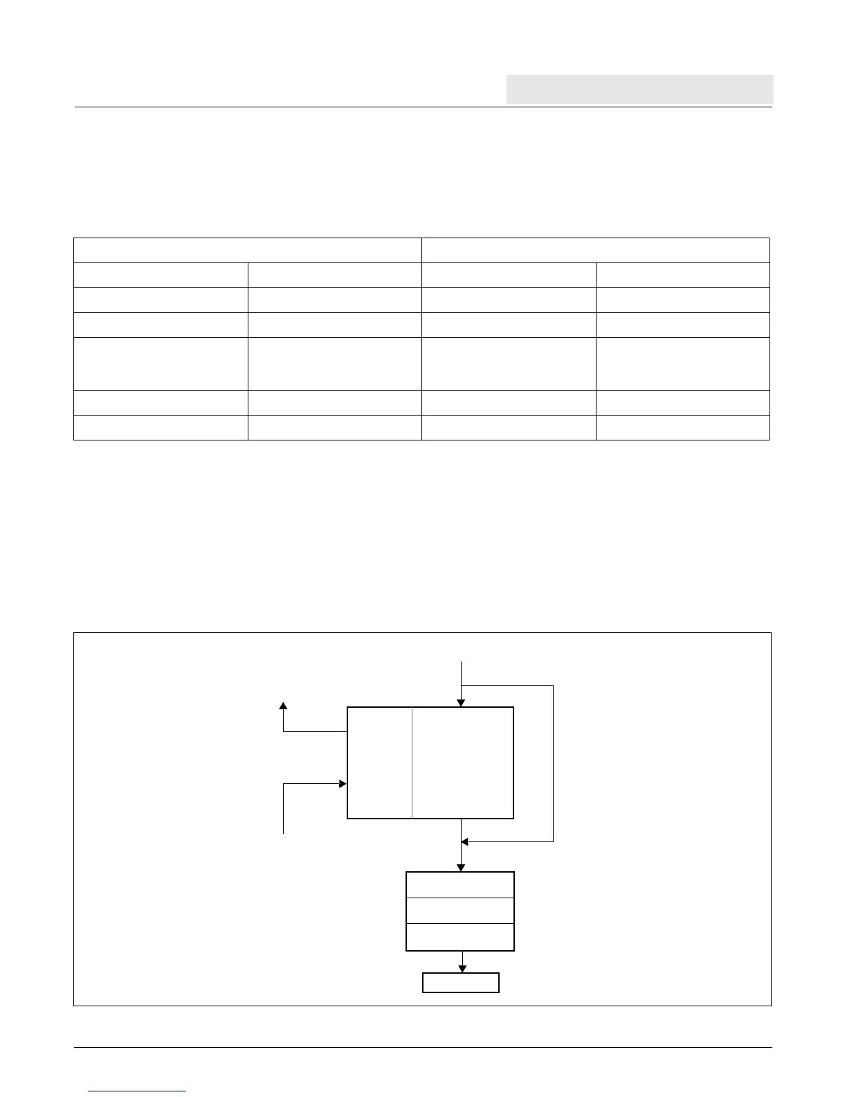
Figure 3-1 shows the relationships between the ICU and the instruction pipeline.
Table 3-1. Instruction Cache Organization
Tags (Two-way Set) Instructions (Two-way Set)
Way A Way B Way A Way B
A
0:21
Line 0 A A
0:21
Line 0 B Line 0 A Line 0 B
A
0:21
Line 1 A A
0:21
Line 1 B Line 1 A Line 1 B
•
•
•
•
•
•
•
•
•
•
•
•
A
0:21
Line 254 A A
0:21
Line 254 B Line 254 A Line 254 B
A
0:21
Line 255 A A
0:21
Line 255 B Line 255 A Line 255 B
Figure 3-1. Instruction Flow
Execute
PFB1
PFB0
Decode
Addresses from Fetcher
Instruction
Arrays
Tag
Arrays
Addresses to Memory
Instructions from Memory
Bypass Path
Instruction Queue