Example
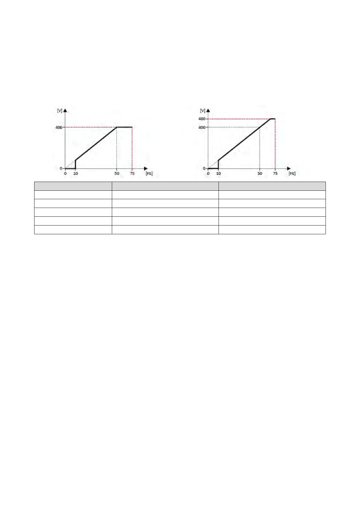
In this example, a 400 V/50 Hz motor is connected to the inverter which is to be operated
with maximally 75 Hz. The minimum frequency is set to 10 Hz.
• V/f characteristic on the left: The inverter is operated with a rated mains voltage of
400 V.
• V/f characteristic on the right: The inverter is operated with a rated mains voltage of
480 V. This causes the output voltage to further increase above 50 Hz.
0x2540:001 (P208.01) Rated mains voltage 400 Veff [1] (on the left) / 480 Veff [2] (on the right)
Next steps
•
The inverter provides different functions by means of which the drive behaviour can be
further optimised.
Optimisation of motor control
122
• A optimisation of the control loops is not mandatory for this motor control type but
may
lead to a better control mode.
Optimisation of the control loops
133