12.16. Configuration of analog outputs
12.16.1. Analog output 1
Settings for analog input 1.
Details
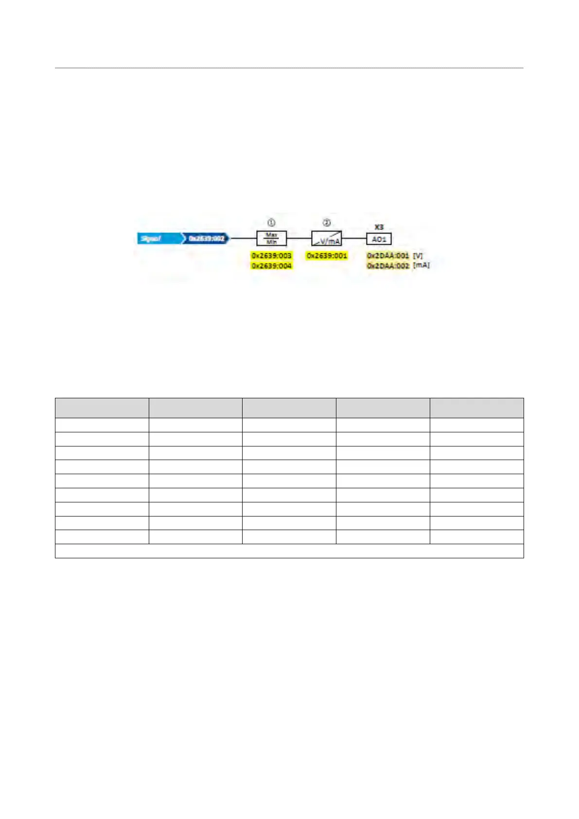
The analog output 1 is controlled with the signal selected in 0x2639:002 (P440.02).
The following settings are possible for the analog output:
• Definition of the signal range
①
• Definition of the output range
②
Diagnostic parameters:
• The current output voltage is displayed in 0x2DAA:001 (P112.01).
• The actual output current is displayed in 0x2DAA:002 (P112.02).
Definition of the signal range
The signal range results from the resolution of the selected signal multiplied by the set min
and max signal value. Signals outside the signal range are cut off. For examples, see the
following table:
Signal
0x2639:002 (P440.02)
Min. signal
0x2639:003 (P440.03)
Max. signal
0x2639:004 (P440.04)
Analog input 2
0.1 %
0
1000
0 ... 100.0 %
NetWordIN4
0.1 %
0
250
0 ... 25.0 %
* 100 % ≡ Motor rated torque 0x6076 (P325.00)
Detailed configuration examples can be found in the following subchapters.
Definition of the output range
The analog output can be configured as voltage or current source. The output range
selected in 0x2639:001 (P440.01) then corresponds to the configured signal range.
Configuration examples
Detailed configuration examples can be found in the following subchapters:
Example 1: Output voltage 0 ... 10 V ≡ output frequency 0 ... 100 Hz
438
Example 2: Output voltage 2 ... 10 V ≡ output frequency 30 ... 60 Hz
439